JCDenton6
Well-known member
Third Age Amps said:Just changed the GAIN pot on my Two-Channel to the 1M and WHAT A DIFFERENCE! Same as what has been posted before. I doubt you would notice much of a tonal difference on a recording, but in the room it has become concussive. Not flabby, mushy bass overwhelming the other tones, just much more movement of the speakers. And that is a MAJOR factor in improving recorded tone. Speaker excursion contributes to the richness and warmth of your tone more than you would think.
Read Slipperman's ramblings and you'll learn a TON about recording distorted guitars.
It's all here:
http://www.badmuckingfastard.com/sound/slipperman.html
Anyway, Three cheers for TheMagicEight's hard work at deciphering a great tone mod!
:mrgreen:
+1 on the recording link!
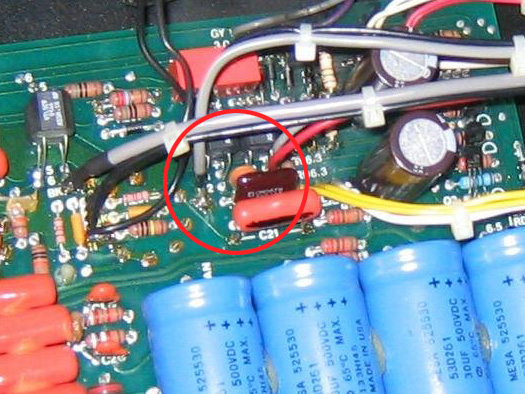
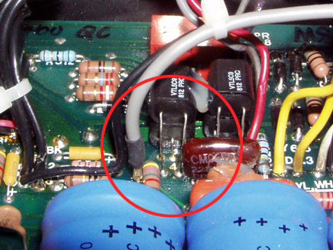
I take it you changed the cap at C55 as well? Or was that change part of your "thunk mod" ?
The change is pretty awesome, I still get surprised by the tone every time I plug in :mrgreen:
")