Shep
Well-known member
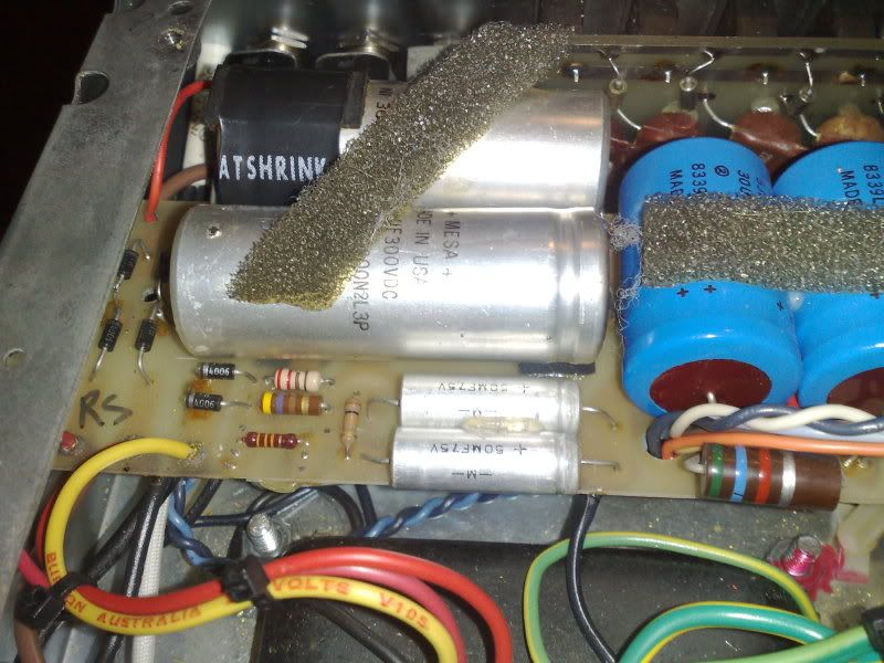
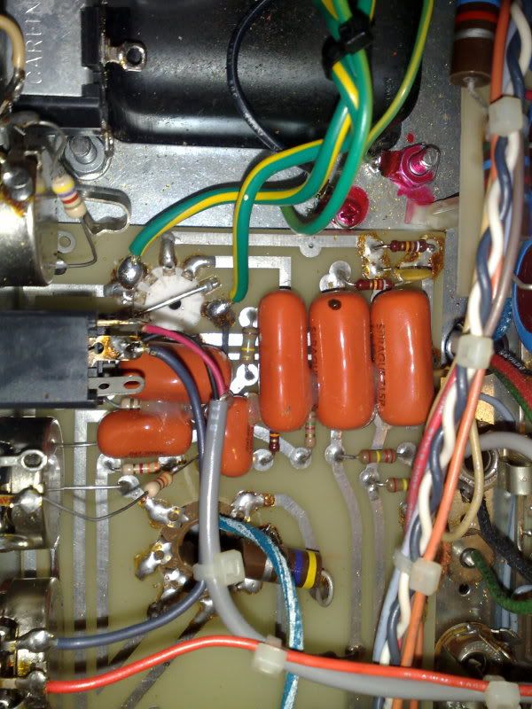
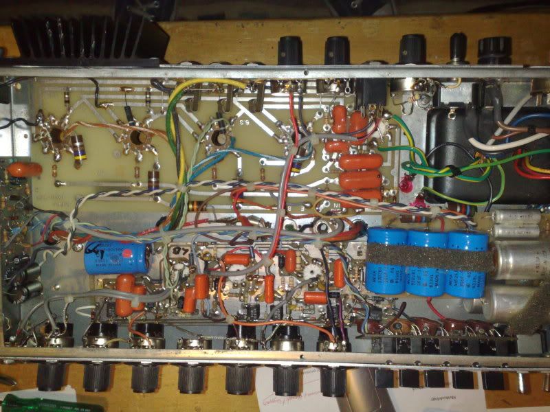
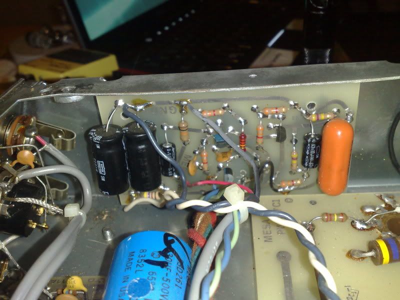
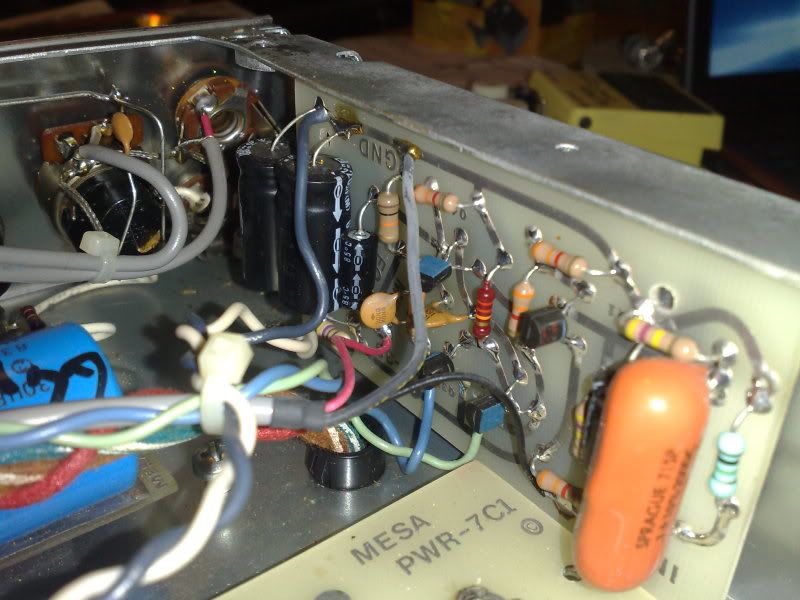
So i am right now goint over my C+ working what cap's i need to replace.I took some photo's of it's gut.
The power Transformer is a blue printed 240volt 105! voltages are spot on with a 105 running 120volts.so i know that isn't orginal.
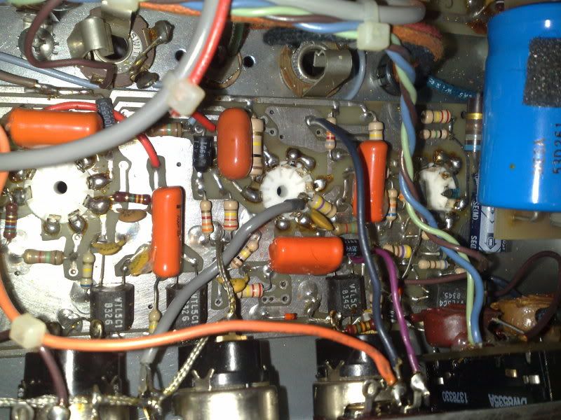
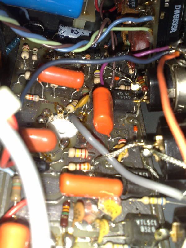
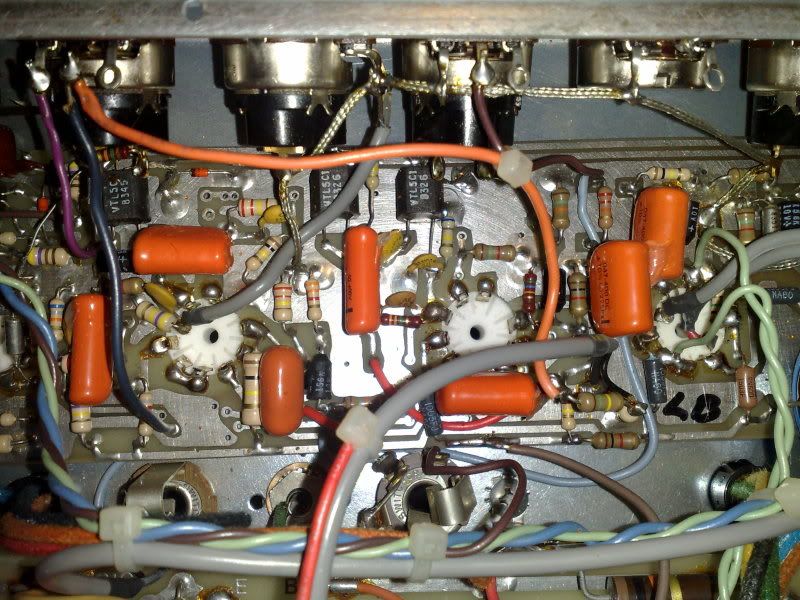
So just wondering What else looks like has been done to it.
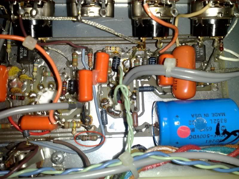
There are some cut resistors on the power supply board that look abit strange.
?
And i looks like to me the bais resistors have been changed on the outer tubes.(they look different?)
Any info would be cool.
Also i am after some bright reduction mod's.
Thanks Alot Tom.
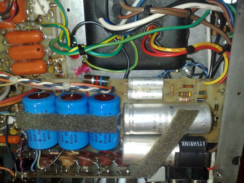

The power Transformer is a blue printed 240volt 105! voltages are spot on with a 105 running 120volts.so i know that isn't orginal.
So just wondering What else looks like has been done to it.
There are some cut resistors on the power supply board that look abit strange.
?
And i looks like to me the bais resistors have been changed on the outer tubes.(they look different?)
Any info would be cool.
Also i am after some bright reduction mod's.
Thanks Alot Tom.