mansfieldguitars
Well-known member
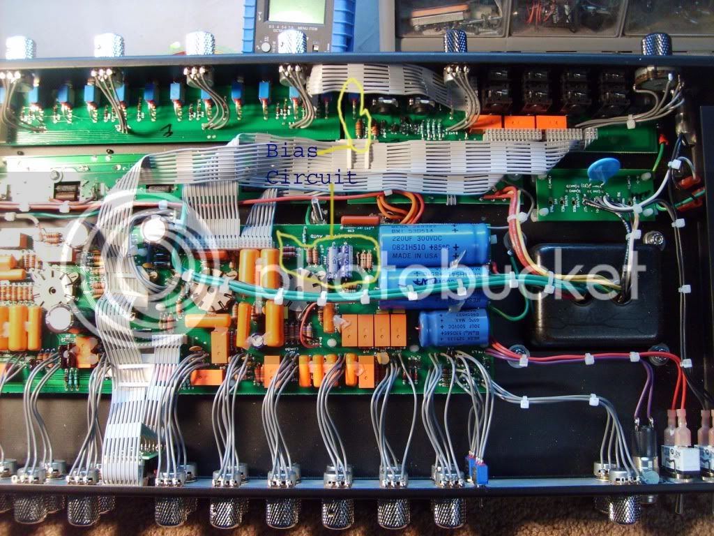
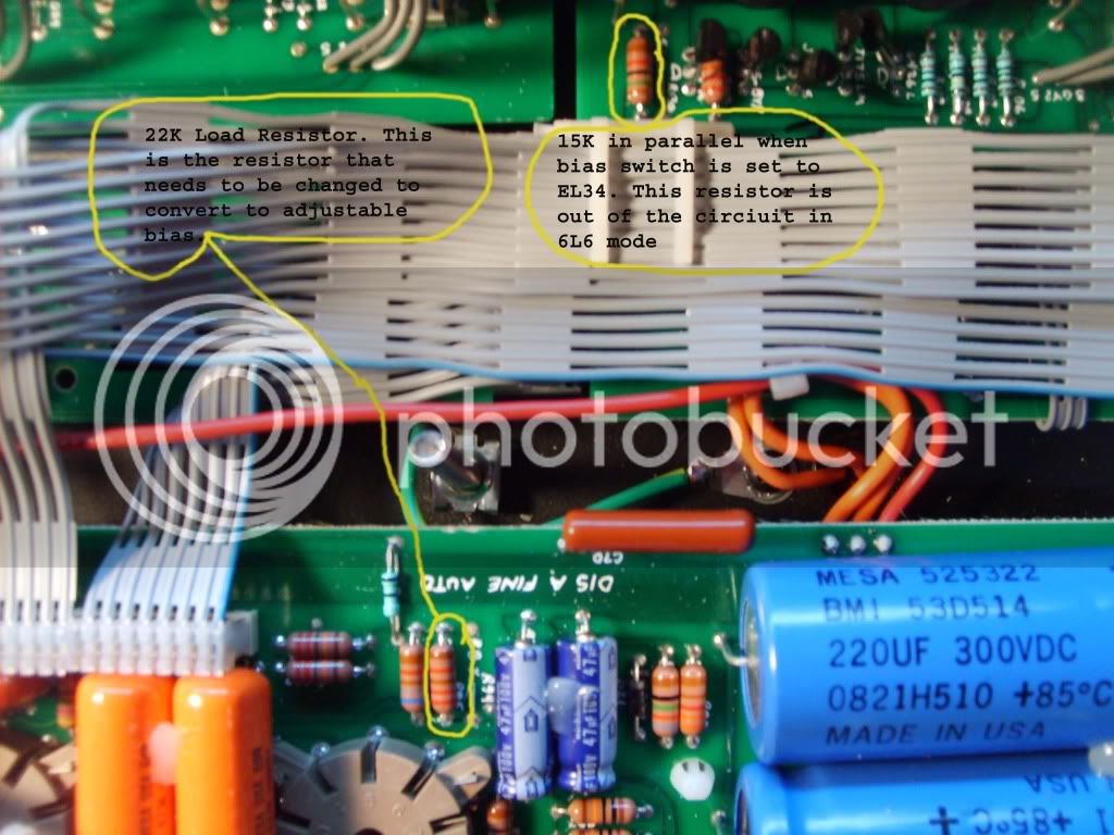
Well I have finally taken the time to trace the bias circuit in my roadster and identify the resistor that needs to be changed. This is the same bias circuit used on the 6L6's in the Roadking II for anyone that might have the schematic for a roadking. The roadster has a fixed 15k resistor for the el34's. The roadking has a trim pot for the el 34's. I have the parts on order to convert mine and when it's done, I'll post some pics. I prefer to add another resistor in series with the trimpot as a safety. A resistor is alot cheaper than replacing burnt up output tubes. To make things look neat and professional I have designed a small PCB board to house the trim pot and resistor with 2 wires going to the holes of the original bias resistor. This assembly is going to be for sale to anyone interested with complete instructions and photos on how to do the mod. For those who are not comfortable with working inside the amp I will also offer installation services. For those DIYers I will post pics of the load resistor in the bias circuit that needs to be changed. Any questions or info on purchasing this mod can reach me at