frets70
Well-known member
- Joined
- Aug 3, 2008
- Messages
- 112
- Reaction score
- 0
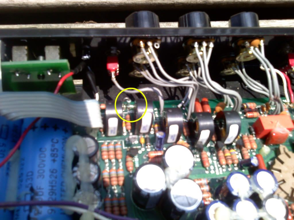
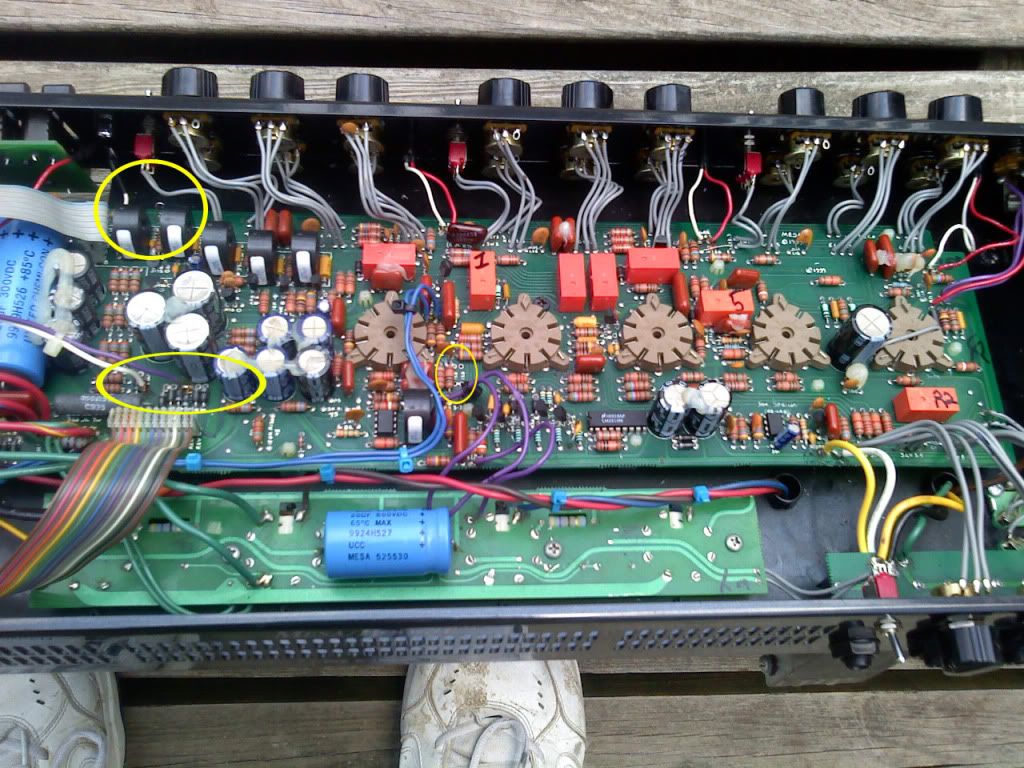
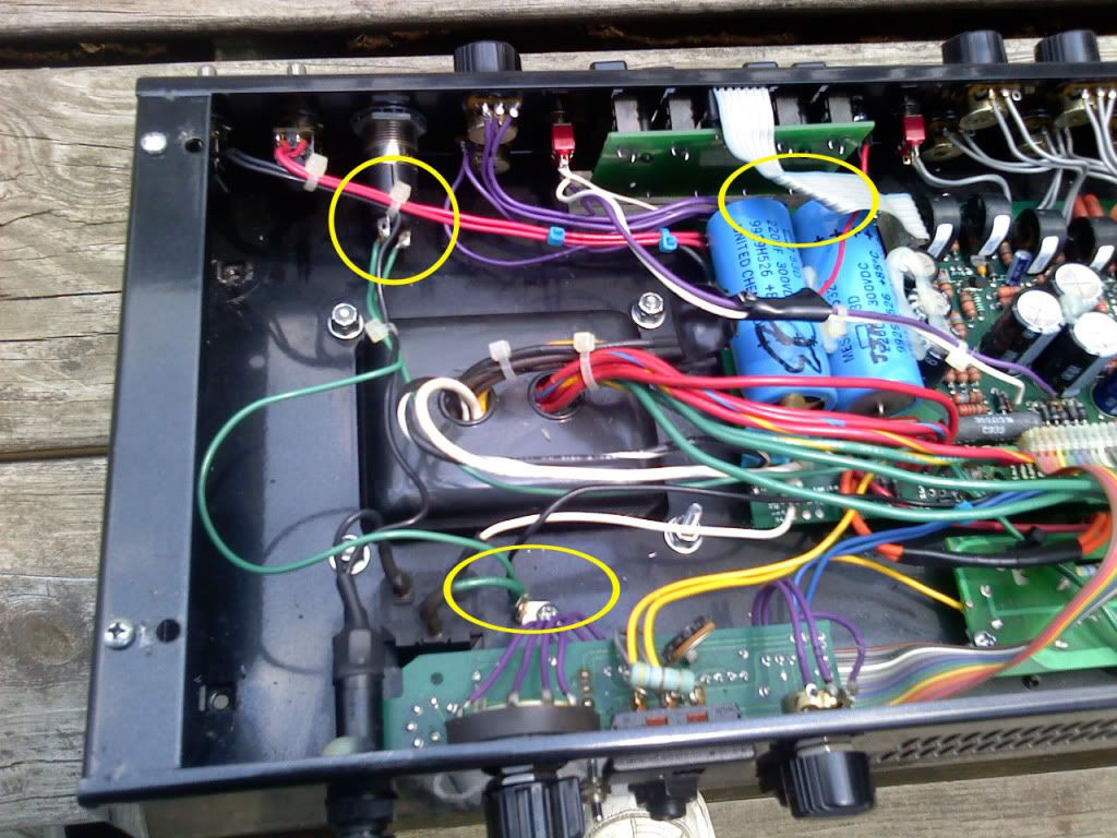
Just picked up a Nomad 100 head in a trade--it's in very good shape, sounds great--I did discover that it had been modified.
It's looks like some sloppy mods, but as I said the head and footswitch function fine except for 2 small things.
1. The Power Jewel light does not come on
2. The EQ indicator LED does not come on
All amp functions are perfect, have played about 10 hours on it with no problems.
My question is this--
without taking it to an amp tech and having it restored to factory spec, are there ways around pulling power from the circuit board to make these indicator lights function correctly?
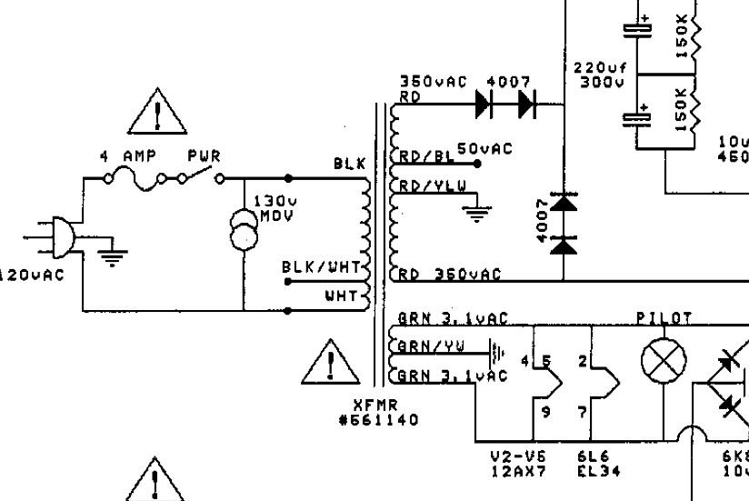
I am including a pic of some of the schematic with the Jewel light power--it seems kinda confusing due to the fact that it shows 3VAC coming into both conductors but no grounding point ( I must admit that I am a schematic noob--but understand electricity very well)
I did get the jewel light to come on correctly by grounding one of the legs, but this may not be correct and also puts the light operating at about half power (3.1 VAC)
I also have figured out how to make the EQ indicator function correctly (seems to me it burned out the original LED due to the fact that the modder slammed it with 3.6 VDC--ouch) I have a new LED that functions at 2.1 volts and just need to pick up a resistor to make it work (as long as my hot connection does not affect the rest of the amp.
Any help would be appreciated, I am not an amp builder, BUT I do know how to discharge caps and do basic component level testing.
Pic below
It's looks like some sloppy mods, but as I said the head and footswitch function fine except for 2 small things.
1. The Power Jewel light does not come on
2. The EQ indicator LED does not come on
All amp functions are perfect, have played about 10 hours on it with no problems.
My question is this--
without taking it to an amp tech and having it restored to factory spec, are there ways around pulling power from the circuit board to make these indicator lights function correctly?
I am including a pic of some of the schematic with the Jewel light power--it seems kinda confusing due to the fact that it shows 3VAC coming into both conductors but no grounding point ( I must admit that I am a schematic noob--but understand electricity very well)
I did get the jewel light to come on correctly by grounding one of the legs, but this may not be correct and also puts the light operating at about half power (3.1 VAC)
I also have figured out how to make the EQ indicator function correctly (seems to me it burned out the original LED due to the fact that the modder slammed it with 3.6 VDC--ouch) I have a new LED that functions at 2.1 volts and just need to pick up a resistor to make it work (as long as my hot connection does not affect the rest of the amp.
Any help would be appreciated, I am not an amp builder, BUT I do know how to discharge caps and do basic component level testing.
Pic below