mikey383
Well-known member
Let me preface this by saying that if you don't feel comfortable working on the inside of your amp, don't do it. Take it to a tech. You've heard this a thousand times already, but tube amps contain lethal voltages, and all it takes is one slip for you to become toast. Furthermore, this takes some soldering abilities. A good medium wattage iron (30 watts or so) is a must...don't use a gun. You'll fry something if you use a gun. I assume no responsibility if you harm yourself or damage your amp. I suggest reading this thread in it's entirety before diving into this project. Pay attention to the pics also.
Second, all I can find are Dual Rectifier schematics. The same principle should apply to Triple Rectos though. These pics are from a 2 channel head, but the same procedure applies to the 3 channel heads as well.
Ok, ready?
First off, start by draining the caps. Power the amp off by flipping the power switch while standby is in the "play" position.
Remove the chassis from the headshell. Using your multimeter on the DC volt setting, check each power tube pin with respect to ground. If you get any voltage readings, let the amp sit until you don't get any. Remove the tubes and turn the chassis upside down.
I took out the Slave pot and installed my bias pot in it's place. Since I swap tubes often due to working with various groups/recording and I keep my head housed in a road case, it's easier for me to have access to the bias pot on the outside of the amp. The choice is yours whether you want to install the pot there or on the inside of the amp. On the 3 channel heads, the Slave pot is on the other side of the amp from the bias section, so you'll have to run a wire down the length of the chassis, which could result in voltage drop. So decide if that's something you want to risk beforehand. If so, remove the slave pot and all wires connecting the pot to the speaker outputs. I removed the wires to the jack too. You'll see why later. If you want to put the bias pot where the Slave pot was, you'll need a suitable pot. I used a Bourns pot. I recommend using a 50K pot. I would give you the part number that I used, but I don't even remember where I got it from and I can't find the exact part online. So, here's a search for 50K pots at Mouser. http://www.mouser.com/Search/Refine.aspx?N=254357+4294571660. If you don't want to replace the slave pot, I recommend a multi-turn trimpot, such as Bourns. Mouser part no. 652-3252W-1-503. FWIW, if you do not change tubes often, I recommend going with the pot on the inside of the amp. It's less prone to get bumped that way.
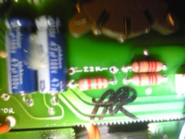
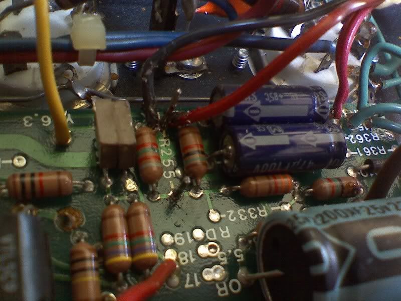
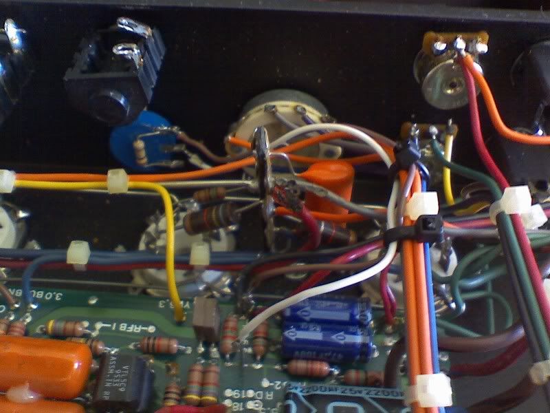
The resistor you want to replace with a pot is a 22K resistor which is in parallel with a 15K resistor (the brown, green, black, red, brown resistor) and two 47uF 100V caps. Here it is on a 2 channel head. Resistor number R255. I already had it removed when I took the pic, but you can see where it was. The resistor I removed was coded red, red, brown, red, brown, so it was actually a 22.1K. Yours may vary slightly also, but should be ~22K. Leave the 15K resistor alone and remove the ~22K. Use this site to figure out the resistors: http://samengstrom.com/nxl/10116/5_band_resistor_color_code_page.en.html
This is in the corner of the PC board opposite the big blue caps. Circled in yellow here:
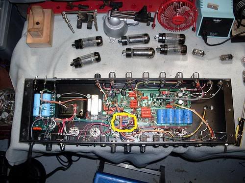
Also, my pics are taken from the other side of the amp...with the front of the amp facing toward me.
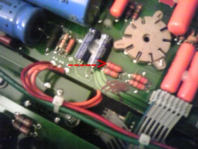
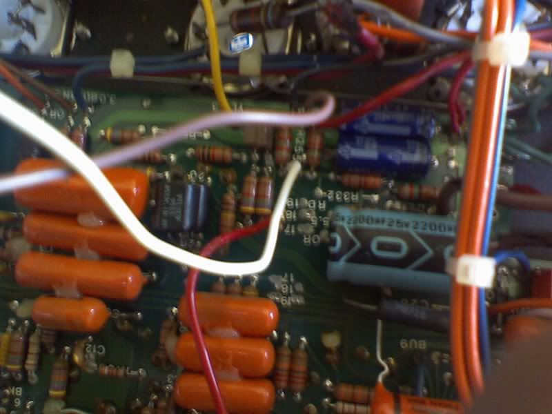
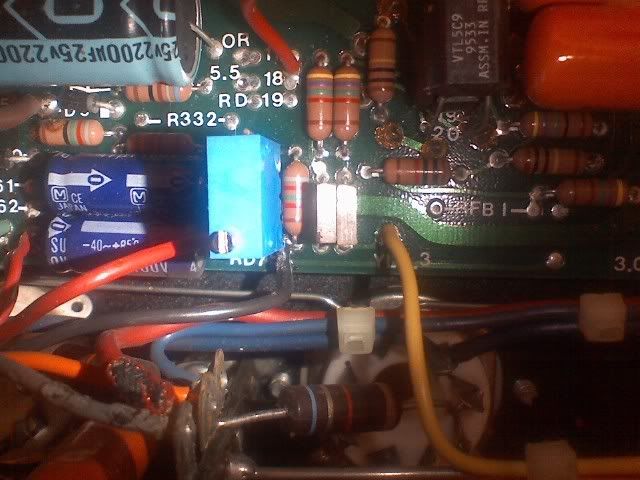
On the 3 channel heads, this section is right beside the big blue caps. There are 2 smaller blue caps to the side of the smallest big blue cap. See the pic for the resistor to replace. The arrow points to the resistor to replace. Thanks to fluff191 for the pic!

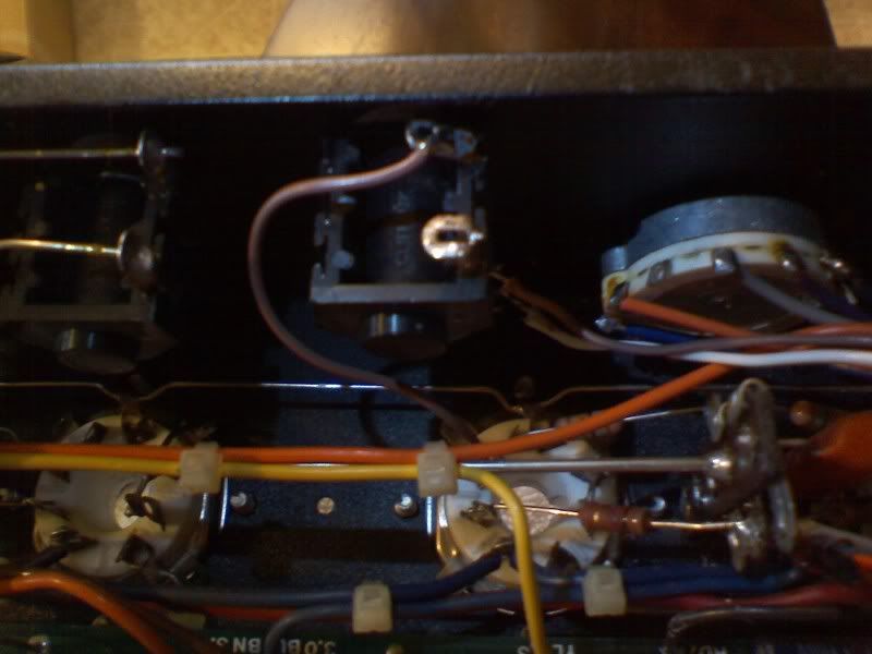
When I took the Slave pot out, I saved the hard wire connecting it to the speaker outs. I used this hard wire to make a couple standoffs that go where the resistor used to. (If you are using the multi-turn pot mounted on the inside of the amp, you can bypass this step. In that case, simply bend the legs of the pot to match the holes in the PCB for the resistor and solder the pot in.)
I then soldered a length of wire to the standoffs. These then went to the pot. One wire went to the middle lug on the pot, one went to an outside lug.
EDIT: I took some of Mansfield Guitar's advice and adapted it. Originally I had a 100K pot with a 100K resistor in parallel with the outside lugs to drop it down to 50K. I just reworked my Recto, and I replaced the 100K pot with a 50K, and used a 56K resistor across the outside lugs. This way I get a 26K total resistance (I measured it). I also tied the center lug to one of the opposite lug that I soldered the wire to. This way, if the wiper loses contact with the pot, the amp sees 26K of resistance, which will run it a little colder than stock. If the pot fails completely, there will be 56K resistance, which will run very cold, but save the amp. The range of adjustment is also much less. HOWEVER, it will still be possible to run your tubes very hot, and this won't save you in case of accidental adjustment. So my advice is to either remember where your pot is set at by using a piece of tape and marking it, or frequently check your bias with a bias probe/multimeter. If you would like to add a safety resistor, simply solder it in series with the pot. See Mansfield Guitar's post on page 5.
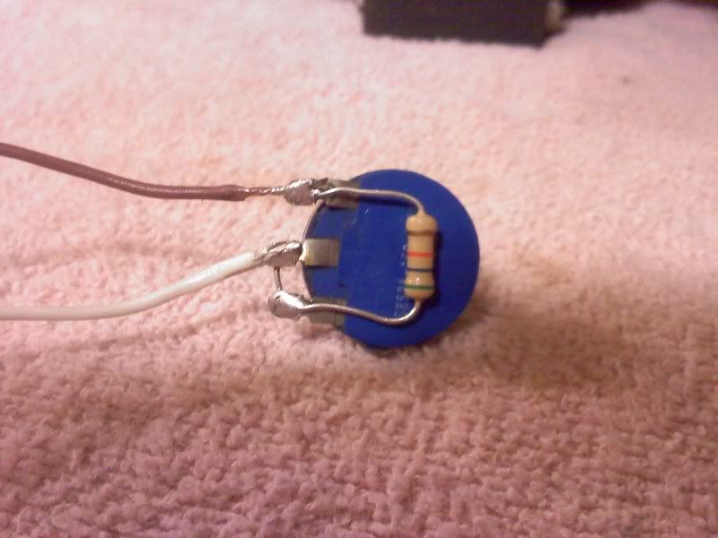
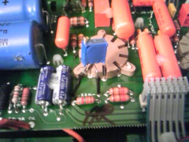
Here's the finished product. The blue pot is my bias pot.
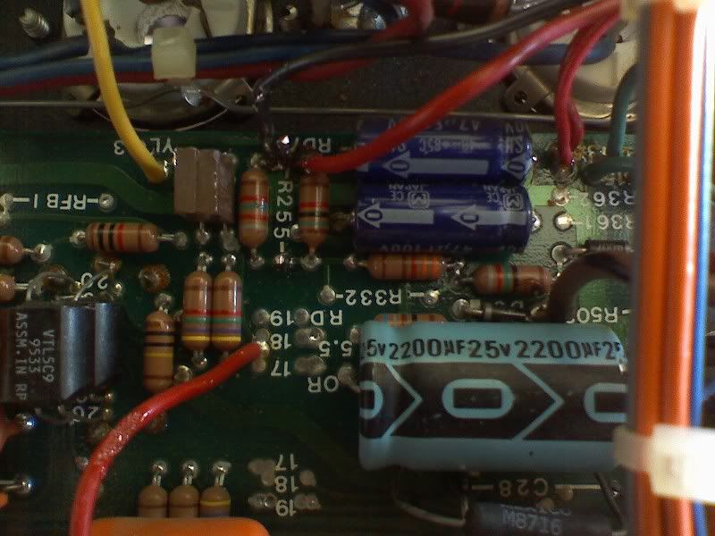
If you chose to go with the multi-turn pot, here's what you'll end up with. Use the middle leg and one of the outside legs. It doesn't matter which one you use. One way will increase by turning CW, the other will increase by turning CCW. I would trim off the unused leg also, or solder it to the wiper so that in case of the wiper losing contact, the amp would see the full resistance of the pot.
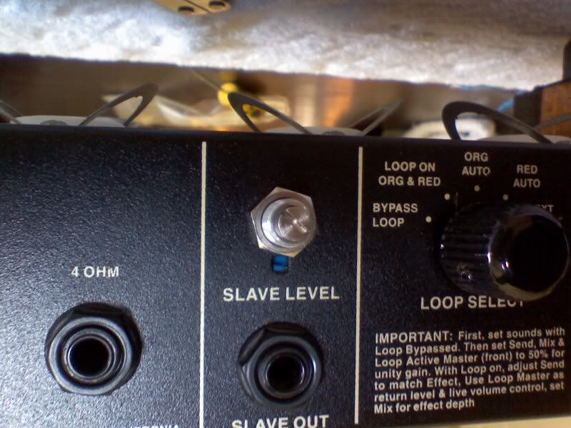
This is the outside view:
Now, you'll want to leave the tubes out of the amp for a moment. Plug the amp in, and make sure both switches are in the off position. Then turn the power switch on. DO NOT FLIP THE STANDBY SWITCH!!! LEAVE IT IN THE DOWN POSITION!!! You're just going to be taking a voltage reading, so this should cause no harm. Measure the DC voltage from pin 5 on a power tube socket (they should be numbered on the underside) to ground. You should have a negative number. Turn the newly added bias pot until you get -51 volts with the bias switch in 6L6 mode, or -39 volts in EL34 mode. This is your factory setting. That will give you a good baseline to start with. The closer the negative voltage is to zero, the hotter the tubes will be. The further away from zero, the colder the tubes will be. Now, turn the amp off, reinstall the tubes, power it back on and let them warm up. Flip it from standby and measure the voltage from pin 3 to ground. You may want to go through all the settings (Bold, spongy, diodes, tube rectifier) and check. Write these numbers down for future reference.
I should also mention that I could only adjust down to -45 volts in EL34 mode. This will still run most EL34s on the hot side. In EL34 mode, I could go clear up to -3 volts, which is WAY too hot. I recommend leaving the amp in 6L6 mode and adjusting the bias that way. In 6L6 mode, I had a full range of adjustment on EL34s. Using 6L6s, the lowest setting got me a little colder than stock, and went way beyond what is usable.
I went one step further and soldered a wire from pin 5 of a tube socket to the old Slave jack. This way, I can insert my meter's probe into the jack and check the voltage without having to disassemble the amp. It's just easier for me that way.
From here, it's a standard bias procedure. There are plenty of resources available on the net showing how to bias an amp. I use a bias probe. These handy devices plug in between your tube and the socket, plug into your meter, and read the current. This is a good link for biasing: http://www.diyguitarist.com/GuitarAmps/PT-Biasing.htm
While I had the amp open, I decided to check for loose solder connections and bad parts. I ended up finding a burnt screen resistor on one of my tube sockets. This would be a good time to replace any bad parts.
If you have any questions, please ask, either in this thread, or you can shoot me a PM.
Good Luck!
Second, all I can find are Dual Rectifier schematics. The same principle should apply to Triple Rectos though. These pics are from a 2 channel head, but the same procedure applies to the 3 channel heads as well.
Ok, ready?
First off, start by draining the caps. Power the amp off by flipping the power switch while standby is in the "play" position.
Remove the chassis from the headshell. Using your multimeter on the DC volt setting, check each power tube pin with respect to ground. If you get any voltage readings, let the amp sit until you don't get any. Remove the tubes and turn the chassis upside down.
I took out the Slave pot and installed my bias pot in it's place. Since I swap tubes often due to working with various groups/recording and I keep my head housed in a road case, it's easier for me to have access to the bias pot on the outside of the amp. The choice is yours whether you want to install the pot there or on the inside of the amp. On the 3 channel heads, the Slave pot is on the other side of the amp from the bias section, so you'll have to run a wire down the length of the chassis, which could result in voltage drop. So decide if that's something you want to risk beforehand. If so, remove the slave pot and all wires connecting the pot to the speaker outputs. I removed the wires to the jack too. You'll see why later. If you want to put the bias pot where the Slave pot was, you'll need a suitable pot. I used a Bourns pot. I recommend using a 50K pot. I would give you the part number that I used, but I don't even remember where I got it from and I can't find the exact part online. So, here's a search for 50K pots at Mouser. http://www.mouser.com/Search/Refine.aspx?N=254357+4294571660. If you don't want to replace the slave pot, I recommend a multi-turn trimpot, such as Bourns. Mouser part no. 652-3252W-1-503. FWIW, if you do not change tubes often, I recommend going with the pot on the inside of the amp. It's less prone to get bumped that way.
The resistor you want to replace with a pot is a 22K resistor which is in parallel with a 15K resistor (the brown, green, black, red, brown resistor) and two 47uF 100V caps. Here it is on a 2 channel head. Resistor number R255. I already had it removed when I took the pic, but you can see where it was. The resistor I removed was coded red, red, brown, red, brown, so it was actually a 22.1K. Yours may vary slightly also, but should be ~22K. Leave the 15K resistor alone and remove the ~22K. Use this site to figure out the resistors: http://samengstrom.com/nxl/10116/5_band_resistor_color_code_page.en.html
This is in the corner of the PC board opposite the big blue caps. Circled in yellow here:
Also, my pics are taken from the other side of the amp...with the front of the amp facing toward me.
On the 3 channel heads, this section is right beside the big blue caps. There are 2 smaller blue caps to the side of the smallest big blue cap. See the pic for the resistor to replace. The arrow points to the resistor to replace. Thanks to fluff191 for the pic!
When I took the Slave pot out, I saved the hard wire connecting it to the speaker outs. I used this hard wire to make a couple standoffs that go where the resistor used to. (If you are using the multi-turn pot mounted on the inside of the amp, you can bypass this step. In that case, simply bend the legs of the pot to match the holes in the PCB for the resistor and solder the pot in.)
I then soldered a length of wire to the standoffs. These then went to the pot. One wire went to the middle lug on the pot, one went to an outside lug.
EDIT: I took some of Mansfield Guitar's advice and adapted it. Originally I had a 100K pot with a 100K resistor in parallel with the outside lugs to drop it down to 50K. I just reworked my Recto, and I replaced the 100K pot with a 50K, and used a 56K resistor across the outside lugs. This way I get a 26K total resistance (I measured it). I also tied the center lug to one of the opposite lug that I soldered the wire to. This way, if the wiper loses contact with the pot, the amp sees 26K of resistance, which will run it a little colder than stock. If the pot fails completely, there will be 56K resistance, which will run very cold, but save the amp. The range of adjustment is also much less. HOWEVER, it will still be possible to run your tubes very hot, and this won't save you in case of accidental adjustment. So my advice is to either remember where your pot is set at by using a piece of tape and marking it, or frequently check your bias with a bias probe/multimeter. If you would like to add a safety resistor, simply solder it in series with the pot. See Mansfield Guitar's post on page 5.
Here's the finished product. The blue pot is my bias pot.
If you chose to go with the multi-turn pot, here's what you'll end up with. Use the middle leg and one of the outside legs. It doesn't matter which one you use. One way will increase by turning CW, the other will increase by turning CCW. I would trim off the unused leg also, or solder it to the wiper so that in case of the wiper losing contact, the amp would see the full resistance of the pot.
This is the outside view:
Now, you'll want to leave the tubes out of the amp for a moment. Plug the amp in, and make sure both switches are in the off position. Then turn the power switch on. DO NOT FLIP THE STANDBY SWITCH!!! LEAVE IT IN THE DOWN POSITION!!! You're just going to be taking a voltage reading, so this should cause no harm. Measure the DC voltage from pin 5 on a power tube socket (they should be numbered on the underside) to ground. You should have a negative number. Turn the newly added bias pot until you get -51 volts with the bias switch in 6L6 mode, or -39 volts in EL34 mode. This is your factory setting. That will give you a good baseline to start with. The closer the negative voltage is to zero, the hotter the tubes will be. The further away from zero, the colder the tubes will be. Now, turn the amp off, reinstall the tubes, power it back on and let them warm up. Flip it from standby and measure the voltage from pin 3 to ground. You may want to go through all the settings (Bold, spongy, diodes, tube rectifier) and check. Write these numbers down for future reference.
I should also mention that I could only adjust down to -45 volts in EL34 mode. This will still run most EL34s on the hot side. In EL34 mode, I could go clear up to -3 volts, which is WAY too hot. I recommend leaving the amp in 6L6 mode and adjusting the bias that way. In 6L6 mode, I had a full range of adjustment on EL34s. Using 6L6s, the lowest setting got me a little colder than stock, and went way beyond what is usable.
I went one step further and soldered a wire from pin 5 of a tube socket to the old Slave jack. This way, I can insert my meter's probe into the jack and check the voltage without having to disassemble the amp. It's just easier for me that way.
From here, it's a standard bias procedure. There are plenty of resources available on the net showing how to bias an amp. I use a bias probe. These handy devices plug in between your tube and the socket, plug into your meter, and read the current. This is a good link for biasing: http://www.diyguitarist.com/GuitarAmps/PT-Biasing.htm
While I had the amp open, I decided to check for loose solder connections and bad parts. I ended up finding a burnt screen resistor on one of my tube sockets. This would be a good time to replace any bad parts.
If you have any questions, please ask, either in this thread, or you can shoot me a PM.
Good Luck!
")