nomad mods

The Boogie Board

Help Support The Boogie Board:

This site may earn a commission from merchant affiliate links, including eBay, Amazon, and others.
i think your confused, the caps don't raise the gain of the PI. just limites the frequencies that are being boosted. probably doesn't not affect dynamics either.
 
nomad100hd said:
i think your confused, the caps don't raise the gain of the PI. just limites the frequencies that are being boosted. probably doesn't not affect dynamics either.

I don't think so. It says exactly this in Koreth's post:
Koreth said:
Conversely, the lower the frequency, the higher the cap's resistance, which in parallel with the plate resistor, presents a greater load to the plate, increasing the gain at lower frequencies. Thus, rather than simply cut everything above a certain point, The highs are cut, and the lows are boosted.

And by dynamic I do not mean playing dynamics. The circuit itself is dynamic reacting differently to different frequencies. Thus, gain is added to lower frequencies (boosting those frequencies), and no gain is added to higher frequencies.

All the best,
 
ok this is how it works.

The bigger the load the more gain. The max load the PI will see is 100K on one side, and 82k on the other. That is the max load any frequency will have on the PI. The caps lower the load for the higher frequencies, but can not present more of a a load for the lower frequencies. Key thing to notice is the plate resistors are in parallel with the caps. thus the resistors are limiting the total resistance any frequency can see.
 
nomad100hd said:
ok this is how it works.

The bigger the load the more gain. The max load the PI will see is 100K on one side, and 82k on the other. That is the max load any frequency will have on the PI. The caps lower the load for the higher frequencies, but can not present more of a a load for the lower frequencies. Key thing to notice is the plate resistors are in parallel with the caps. thus the resistors are limiting the total resistance any frequency can see.

I understand the bigger the load the more gain. I am not trying to be argumentative, I am just trying to reconcile/understand Koreth's explanation and extend my knowledge of things. I may be missing something, but he seems to say the exact opposite of what you just wrote. You say "caps...can not present more of a load for the lower frequencies." Is Koreth referring to something else, because the quote below says "the higher the cap's resistance, which in parallel with the plate resistor, presents a greater load to the plate, increasing the gain at lower frequencies" (i.e., boosting the lows).
Koreth said:
...the higher the cap's resistance, which in parallel with the plate resistor, presents a greater load to the plate, increasing the gain at lower frequencies. Thus, rather than simply cut everything above a certain point, The highs are cut, and the lows are boosted.
[/quote]

If you think this is wrong, that is fine. However, I was basing my original question on Koreth's information. I do not mind being wrong. It is the best way to learn things.

All the best,
 
I'll admit, I'm a layman. My understanding of electronics has come from reading pages graciously linked to by Google and hanging out on forums with people smarter than me and listening to what they have to say. By the by, the correct term in my original explanation about the capacitor's behavior is reactance, not resistance, which has the same effect on AC that resistance has on DC, but is not the same thing. But a capacitor's reactance does increase the lower the frequency, approaching infinity as it gets closer to 0 Hz/DC. Whether my original explanation or Nomad100hd's is the totally correct one is probably splitting hairs, arguing semantics and possibly even making EEs cry at this point. Ultimately, the effect of the plate bypass caps is that the highs get less gain, and the lows get more.
 
my point was since the cap is in parallel with the resistor the total resistance can't be more than the resistor.
 
Upon this we can agree. When I was using the terms greater and lesser speaking of the impedance at the plate, I meant relatively with regard to the highs and lows in relation to each other. I did not mean to imply that the bypass cap somehow made the plate resistors appear larger than their rated values.
 
Koreth said:
The crossover points you listed are the -3 dB points if the PI bypass caps were a lowpass filter. But placing the bypass cap in that position creates a shelving filter instead. The cap's resistance at high frequencies is much lower, acting as a low value resistor in parallel with the plate resistor, presenting the tube with less load resistance at high frequencies, reducing the gain at those frequencies. Conversely, the lower the frequency, the higher the cap's resistance, which in parallel with the plate resistor, presents a greater load to the plate, increasing the gain at lower frequencies. Thus, rather than simply cut everything above a certain point, The highs are cut, and the lows are boosted. This would by why some find the Nomad muddy. Cutting highs is one thing, but cutting highs while boosting lows is going to create a muddy sound. Try it on your favorite stereo sometime. Turn up the bass while turning down the highs. Going too far will make for a muddy sound.
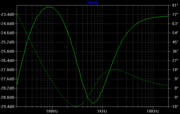
Any low frequency boost would be a perceived boost, as there is no actual boost of the low frequencies caused by the caps, only a reduction of the higher frequencies at the referenced -3dB point. Do you hear a noticeable difference in the recordings I made of the before and after? To me, the results of mod are questionable but I wouldn’t completely rule it out as a good mod, I’m just saying that the difference is very subtle at best. Also, on the flip side, I found removing some low end on the input seemed to have a more pronounced effect in my case, I think this is because it is effectively the same approach, only instead of adding more of the higher frequencies I cut some of the lower frequencies and the -3dB point of my mod is more in the audible frequency range of the guitar. I didn’t mean to say that this mod is not a good mod, I’m only saying that the effect is very subtle and may not solve all your muddiness problems.
 
Koreth said:
Upon this we can agree. When I was using the terms greater and lesser speaking of the impedance at the plate, I meant relatively with regard to the highs and lows in relation to each other. I did not mean to imply that the bypass cap somehow made the plate resistors appear larger than their rated values.

Hi Koreth,

Unfortunately, I was interpreting "greater and lesser" as changing the plate load resistor's value. However, I was not or did not intend to say that the bypass cap could make the plate load resistor appear larger than their rated value. But it can change the gain. The gain of the tube is determined by the relationship of the Rk (the cathode resistor) and Ra (the anode or plate load resistor). A book I have, "The Ultimate Tone" by Kevin O' Connon, given to me by one of my EE colleagues has some material on this. Although O'Connor is talking about a cathode bypass, I think the idea is the same (pp 4-8 and 4-9):

"At this point, we should look at the effect of the cathode bypass capacitors. We have seen that the gain of each triode amplifier is determined primarily by the values of Rk and Ra. With no cathode bypass capacitor, all frequenceies are amplified equally. Connecting a cap across Rk introduces an RC time constant which causes the gain to become frequency-dependent."

This is what I was thinking about when I said the circuit was dynamic. It should be the same for connecting a cap across Ra. Interesting enough, O'Connor has a section on the Boogie circuit for cutting high frequencies:

"There are methods to reduce the high frequency gain of the individual stage as well. The most popular method is to bypass the anode resistor with a small capacitor. Because of the usually high values of Ra, combined with the high roll-off frequencies chosen, a capacitor value of 100pF to 1nF will give break points of 16kHZ down to 1.62kHz when placed across 100kohm. This method of bandwidth restriction is used most often by Mesa-Boogie. The only potential problem with this technique is the loading on the tube and the interaction of the new cap with the interelectrode capacitances of the tube. It is best to place a small resistor in series with the cap, or to bypass only a portion of the anode resistor...The series resistance with the fully bypassed anode resistor is the recommended method, as it helps to isolate the tube capacitances from the add cap. In this case, the minimum load resistance seen by the plate of the tube is equal to Rs, the series resistance. The frequency where the high-frequency gain starts to drop is set by Ra and Ca."

I just thought this might be interesting additional information. If anyone is interested, he has diagrams of the circuit with the added resistors. I can scan them and post them. Thanks for the good discussion, and this is why I love the Boogie Board, always learning new stuff.

All the best.
 
Koreth said:
timowens said:
I too struggle with the muddiness of my Nomad 55. Whenever I found this thread about the PI mod I was curious because a 120pF in parallel with a 100K crosses over at 13,263Hz and an 82K & 120pF at 16,174Hz. To me this would seem pretty much inaudible in a guitar amp so I figured they were to help prevent noise and oscillation but since I had to open my amp up anyway to work on one of the pots (don’t you hate the pots in the Nomad) I thought I’d try the mod. I took some pictures if anyone wants and I also recorded some before and after clips to see if I could really hear the difference. To me, it is real hard to hear the difference, on ch-3 with high-gain it is really hard but with ch-1 and ch-2 there might be a noticeable difference. I didn’t spend any time dialing in any tones and I didn’t spend any time adjusting the mic placement for the recording but for an A/B comparison the test should suffice. First I started off with ch-3, then I switched to ch-2 and ch-1 and back to ch-3. The only discrepancy would be when I backed off the volume on the guitar, I didn’t pay attention to how much I exactly backed it off between the two recordings but it should still give you an idea of the difference.

I think I will leave this mod in for now even though its effectiveness is questionable. I would like to say though that I did do another mod that seemed to help more for my setup. Since I use humbuckers I always struggle with too much bottom end, especially in high-gain settings, it just seems to really get muddy on the low notes. To tighten it up I replaced a .02 cap on the input circuit (C32 I think) with a .0022 cap and it really helps, I’m even thinking of going a bit smaller. I have pics it anyone is interested.

You can hear the test clips of the before and after PI mod at http://www.soundclick.com/timowens

The crossover points you listed are the -3 dB points if the PI bypass caps were a lowpass filter. But placing the bypass cap in that position creates a shelving filter instead. The cap's resistance at high frequencies is much lower, acting as a low value resistor in parallel with the plate resistor, presenting the tube with less load resistance at high frequencies, reducing the gain at those frequencies. Conversely, the lower the frequency, the higher the cap's resistance, which in parallel with the plate resistor, presents a greater load to the plate, increasing the gain at lower frequencies. Thus, rather than simply cut everything above a certain point, The highs are cut, and the lows are boosted. This would by why some find the Nomad muddy. Cutting highs is one thing, but cutting highs while boosting lows is going to create a muddy sound. Try it on your favorite stereo sometime. Turn up the bass while turning down the highs. Going too far will make for a muddy sound.
It has been a long time, but I have some new information as it relates to the de-mud mod. In the past couple months, I have figured out how to use one of the variants of SPICE, LTSpice for those of you who care. For those not in the know, SPICE is a general purpose analog electric circuit simulator. While it is very powerful and can be used to simulations to aid in the design of Integrated circuits and PC boards, it can also do simulations of vacuum tube amplifiers, since our amps are analog circuits. After finding some models for the 12AX7 tube, I was able to model various parts of the Nomad circuit and see their frequency response. In the process, I learned a few things that I want to share, which should allow us to make a much better, more effective de-mud mod that is as subtle or dramatic as we want.

First, I'll start by retracting my above statement with regards to the crossover points plate bypass capacitors in the phase inverter. Tim is correct, the crossover points of of 100k? and 82k? resistors in parallel with 120 pF capacitors are way above the frequency range of interest for our guitars, up past 10kHz. We'll get to that in a minute but let's take a quick detour.

Let's be honest with ourselves. Our guitars aren't high range instruments, they're mid range instruments. Even the nastiest, fizziest, fuzziest tone with too much high order harmonic content isn't going to have much happening past 10khz. Let's take the 17th fret on the high E string. If the guitar is tuned to standard concert pitch, that note is A5 @880hz. The harmonic frequencies for 880hz are: 1.76kHz, 2.64kHz, 3.25kHz, 4.4kHz, 5.28kHz, 6.16kHz, 7.04kHz, 7.92Khz for the 2nd-9th harmonics, respectively. You'll notice that we didn't get past 8kHz, much less past 10kHz. The highest fretted note of a 24 fret guitar, E6, has a fundamental frequency of 1318.51hz, which gives us a 9th order harmonic of 12.43khz. That's the 9th order harmonic. The higher order harmonics aren't going to be as strong in relation to the fundamental as the lower ones, and furthermore we don't want them to be. Those high order harmonics sound nasty and harsh.

So our guitar isn't going to be putting out much past 10kHz, and so anything above that, we can ignore as far as amplification goes. Related to that, guitar speakers aren't going to be producing much beyond 5-7khz anyway. If we look at the frequency response graph for the Celestion V30, we can see at 5khz, speaker's volume starts diving down sharply and by 7.5khz, it's about as low as it's going to get. The Classic Lead 80 (what the C90 is supposedly based upon) does similar. It starts rolling off upper mids and highs at 3kHz and keeps going down all the way to 20kHz. We see similar high frequency roll off in other popular speakers like the Greenback, the G12H, the G12T-75, and others.

Is there a point to this? Yes there is and it is this: Anything above 10kHz we can disregard. If a mod isn't getting a change in freq response below 10Khz, we're looking in the wrong place.

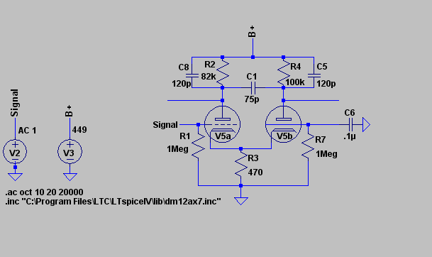
Which brings us back to the original de-mud mod and Tim's thoughts on it. He's right. Removing the plate bypass capacitors in the phase inverter isn't going to have a change in frequency response low enough for us to worry about tonally. The results of the SPICE simulations I ran support this notion, IMO. Below is a circuit diagram of the Nomad's phase inverter, as it appears in the schematic.

NomadPISchem.png

Omitted are the tail resistor and the feedback resistors as a) they would have required simulating the rest of the power amp, power tubes, transformer, feedback loop and all, and b) we're interested mainly in the effect the plate bypass caps have on the freq response of the phase inverter itself vs the power amp as a whole. Also omitted are the previous stages of the amp and the power supply. These can be approximated with voltage sources, which are the little circles on the left.

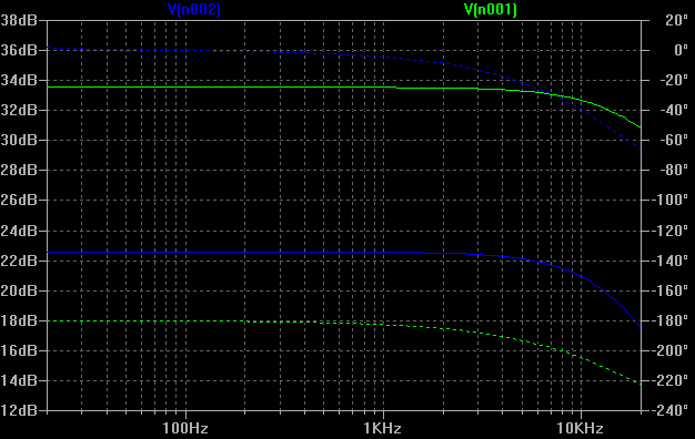
NomadPIFreq.png

This is the graph showing the output gain of both triodes in dB vs frequency, from 20 to 20khz. Notice how the high end freq response doesn't start dropping until close to 10kHz, and isn't down -3dB until after 10kHz. So it is doubtful that we're loosing enough highs here in the phase inverter to get a muddy sound. But just to be sure, let's compare what happens when the plate bypass caps are clipped out of the circuit.

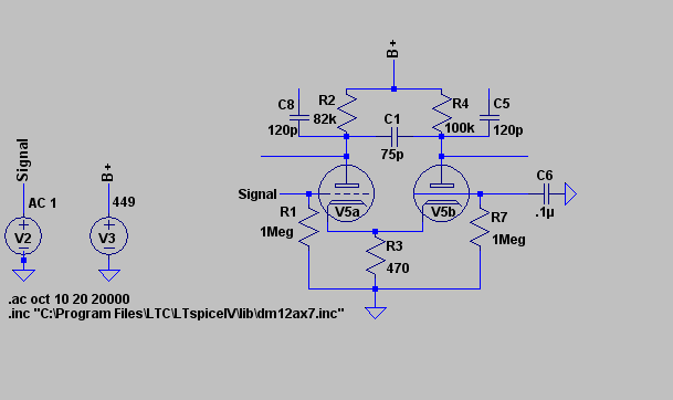
NomadPISchemMod.png

Here's the PI without the caps.

NomadPIFreqMod.png

And here's the change in freq response. There is no dramatic increase of highs below 10kHz. One half of the phase inverter does start to get more gain on the high end starting just before 10khz, but it isn't up 3dB yet by 20Khz. However, if gain does keep increasing through the supersonic range and into the RF range, it is conceivable that the amp could pickup noise or even become unstable and oscillate. So, the likely purpose for these plate bypass caps is to suppress noise and oscillations, and not to shape tone by rolling off audible highs. Some of the Mark series amps have a plate bypass cap in the phase inverter, and they aren't generally considered muddy amps. Now, I have not yet heard of anyone having oscillation, instability or noise problems from doing the de-mud mod. There's plenty of high end attenuation earlier in the signal chain, so these plate bypass caps are not the straw that breaks the camel's back. However, make changes earlier in the circuit that brighten the amp up and there could be a risk of it.

Understand that I'm not trying to invalidate anyone's satisfaction with their tone. If you have done the de-mud mod and are now happy with the sound of your Nomad and the tones you get from it, rock on, dude! More power to you. Likewise if you have a stock Nomad and are happy with the sound. For those of you who haven't done any mods, and find the Nomad muddy, or have your doubts with the de-mud mod as it stands, read on.

So, if the mud of the Nomad isn't coming from the phase inverter, where is it coming from? From the post that started this thread:
nomad100hd said:
What if i could say that removing 2 capacitors would fix the muddiness of the nomad? I did some experimenting took the FX loop out into the FX loop in of another amp. I was floored no muddiness amp was real lively! hmm so the mud is all in the power amp! Well i forum'ed a bit and it's been suggested the capacitors on the PI's load is the source of mud!. As soon as i get a chance i'm going to remove them.
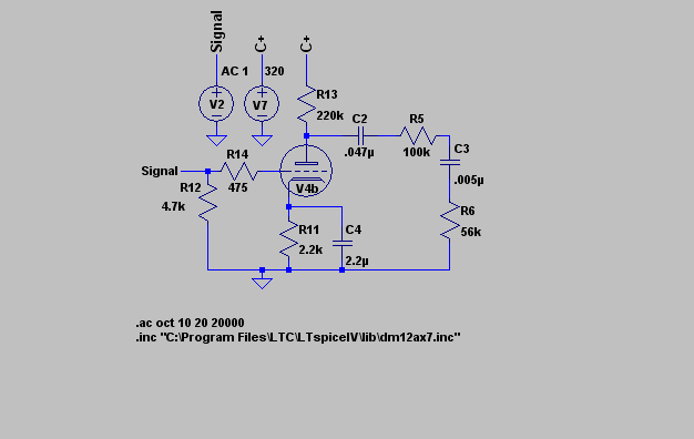
Well, the only other points between the preamp and the phase inverter are the Graphic EQ on the 100W models and the FX loop return/recovery stage. Since muddiness is a complaint with the 50W model, it is unlikely that the EQ is the source of the mud. Furthermore, the EQ sits before the FX send, so if it was the source of the mud, nomad100hd wouldn't have had the results he did. That leaves us with the FX return stage. Just in case anyone thinks "Wait, that's the FX loop, it doesn't do anything unless I'm running effects, and my Nomad sounds muddy all the time, not just with FX in the loop," or anything similar trying to justify why the FX loop can't be affecting the sound, take a very close look at the schematic. The signal passes through the FX recovery stage all the time, whether the FX loop is in use or not. So lets run a simulation of FX recovery circuit and see what effect, if any, it has.

NomaFXSchem.png

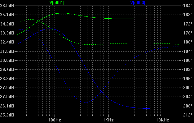
Here's the circuit, as shown on the schematic. Again, we're using voltage sources to approximate the power supply and the signal from the previous stage, and doing an AC sweep from 20Hz to 20kHz

NomadFXFreq.png

And here's the frequency vs Gain graph for the FX recovery stage. Green is frequency response before the coupling cap. It is fairly flat, with a slight bump in the lows/low mids - nothing spectacular. Blue is taken after the coupling cap at the node of the 100k/56k divider and that .005µF treble bleed cap. Yikes! Look at that! a bump in the lows/low mids, and then it start rolling off sharply. We're down -3dB by 300hz, and have bottomed out by 3kHz. Look at that blue line, that's all lows and low mids, with all the mids and higher getting sucked out. If that isn't a recipe for muddy tone, I don't know what is.

It is now 2am and I'm tired. I'll address potential solutions in my next post. And just to stave it off now in case it comes up, understand I am not trying to attack nomad100hd's or his efforts here. The fact that he took the time to try to isolate the source of the Nomad's mud and came up with a mod to try to do something about it, and then proceeded to share this with us speaks volumes about him. If it wasn't for his efforts I probably never would have thought trying to do something about the problem, and probably would have sold my Nomad off for, I dunno, a Marshall or something. So, yeah, I owe nomad100hd some thanks here for kicking off the whole idea of modding Nomads for better tone. Anyone here ever has a chance to hang out with this guy, buy him a beer or something.
 
I'm glad someone still digging into the nomad. Mine has become undependable, glitches in the switching matrix, just plan worn out. I got in a pinch and had to buy a new amp, the store had no Mesa heads in stock so i bought a Randall Rm100, it's one of their modular amps. When i get sometime, i'm going to pull the board out and really go threw the amp. I have a feeling the tone stack on channel 3 needs a lot of work.
 
To be fair, I haven't done any actual physical digging into the my amp as I've needed it operational for rehearsals and shows. So figuring out how to model bits of the Nomad circuit in SPICE, or any tube circuit for that matter, has been a Godsend when it comes to learning how these mysterious glass bottles interact with the rest of the amp and make the magic sounds they do. When one considers that hitting a PC board with a soldering iron too much can kill the board, I'm especially glad I can simulate in SPICE what will happen before taking the risks of open heart surgery with the Nomad.

So, we have shown that the FX loop recovery stage is attenuating all frequencies past 100hz Well, why? And what to do about it? Let's take another look at the schematic for that stage. and it's frequency response

NomaFXSchem.png

NomadFXFreq.png

The green line shows the frequency response of the stage as it exits the valve, but before it has crossed the output coupling cap. The blue line is it taken at the knee of that voltage divider/low pass filter, formed by the 100k resistor, 56k resistor and .005µF capacitor. That capacitor is bleeding off high frequencies to ground, and due to it's size is actually bleeding off quite a lot. What were to happen if we were to make it smaller by an an order of magnitude, from .005µF/5nF to 500pF?

NomadFXFreqMod1.png

That's a bit better. We've got our mids back now at least, but we're still loosing some of our top end. Let's see what happens if we shrink the cap again by another order of magnitude, from 500pF to 50pF.

NomadFXFreqMod2.png

That's much better. Frequency response is nice and flat for most of the range of interest. Sure, the highs and lows are being rolled off a bit, but the lowest part of the lows were getting rolled off anyway, and at least now, freqeuncy response on the high end isn't down until past 10kHz. The rolling off of high frequencies should still prevent any instability or oscillations, especially if the phase inverter caps are still in place, unless there's a problem elsewhere in the amp.

So, here is what I propose for a De-Mud Mod - Mk II(C+? :p) change the .005µF cap on the output of the FX loop recovery stage to a 50pF cap. the nearest 5% standard value, 51pF or 10% standard value, 47pF should work fine too. This should stop the attenuation of all the midrange and high range through the FX loop while still bleeding off enough high range frequencies to prevent instability.

Nomad100hd, since you have an interest in tweaking the Ch3 tone stack, I'll run some simulations of that next.
 
While individually, said cap may or may not be necessary, it is there for a reason. I doubt the engineers at Mesa are in the habit of just adding parts to a design for sh!ts and giggles. Not just the Nomad, but other Mesa amps have little treble bleed caps scattered across the across the circuit. It is entirely possible that it is necessary to prevent high frequency oscillation. Maybe it was necessary in the prototype, and carried over to the production version, but isn't necessary now. Maybe it is only intermittently necessary when the amp is in a noisy environment. I don't need my amp going into wild oscillations at a show because the stage of the venue I'm playing at happens to be next to the building's telephone closet, or some jerk two blocks down is running a pirate radio station.

If I didn't think these concerns were justified, I wouldn't voice them. Let me explain why I think that cap may be necessary. It involves a quick lesson in how tubes work, but I'll try to keep it simple as possible. All vacuum triodes have a capacitance between their electrodes. It is usually small, on the order of a handful of pF, but it is there. A funny thing about using a triode to make a gain stage is that the capacitance between the plate and grid is amplified along with any signal entering the tube. So if we have 5pf from the grid to the plate, and the circuit the tube sits in gives a gain of 50, that measly 5pF just became a much bigger 250pF. Combine that with the grid to cathode capacitance and any resistance present at the grid and we get a low pass filter, the corner frequency of which is determined by the input restance that the total capaciance in the tube. This is called the Miller Effect one of the reasons why tetrodes and pentodes were invented. The additional grids effectively shield the plate from the grid, eliminating this problem. However, this does not prevent triodes from being used for their original intended purpose: RF work. Configured properly, a triode can absolutely detect and amplify RF.

In guitar amps, this one of the reasons we see resistors on the grids of the tubes. The 68k? resistor found on the grid of the input stage of most classic Fender and Marshall designs worked with the Miller capacitance of the tube to make a low pass filter w/ a corner freq of 23.6kHz. That's just past the 20kHz limit for audio work and ensures that any stray RF noise doesn't get into our guitar amp through the input. That's good design. However, let's consider the FX recovery stage in the Nomad. It has only 475? on the grid, and combine that with with the 220k? plate resistor, we have a gain of 77 all the way up to 2.6MHz. That's well into the RF band. Any stray RF that the amp picks up at or before the FX loop that isn't attenuated before the recovery stage is going to get a huge dose of gain and possibly become big enough to make the amp unstable at RF and cause oscillation problems. And while the cables that connect devices to the FX loop are (or should be) shielded, thus dumping any stray RF to ground, the units in the FX loop might not be so well designed or behaved. The engineers at Mesa/Boogie can't reasonably be expected to figure out what FX boxes do and and do not cause the amp to become unstable, so they take a safer, more consistent route and throw a cap in there to bleed off any unnecessary high frequencies.

If you choose to pull the cap from the circuit and bypass it entirely, and it works to solve the mud problem without making the amp unstable, rock on. I choose to err on the side of caution.
 
Edit: Okay, fixed the simulation and generated new graphs.

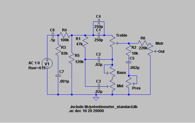
Here are some tonestack simulations, as promised.

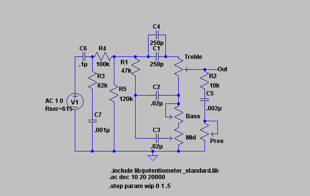
NomadToneStack1.png

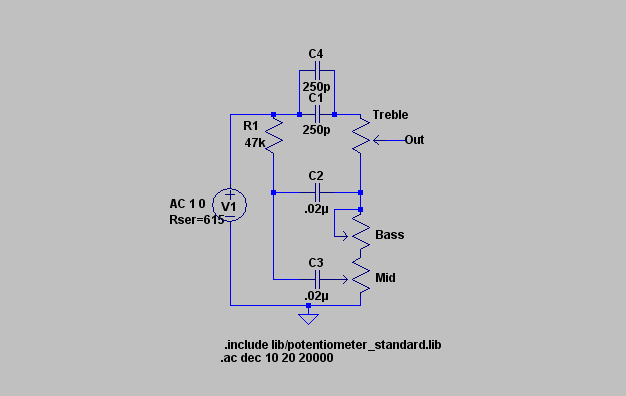
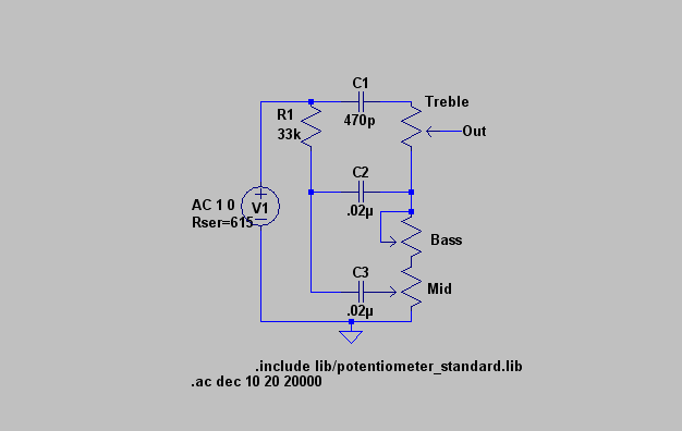
Here is the Nomad tone stack. The voltage source with a series resistance of 615ohms approximates the cathode follower with a 100k? load resistor. You know, this looks familiar. Where have I seen this circuit before?

MarshallToneStrack.png

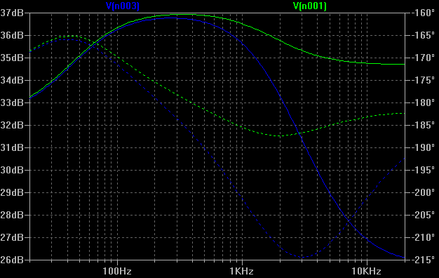
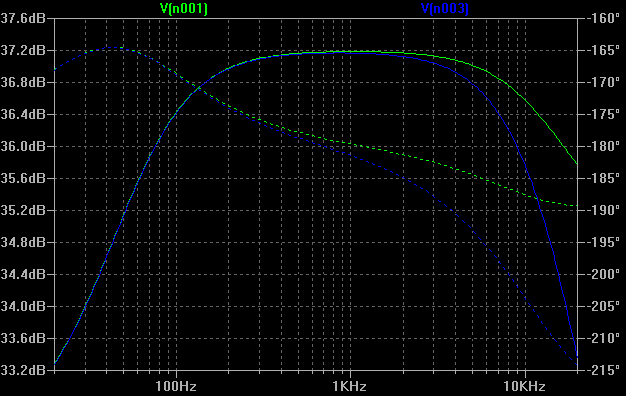
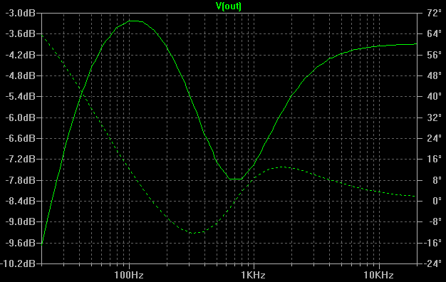
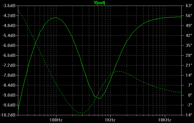
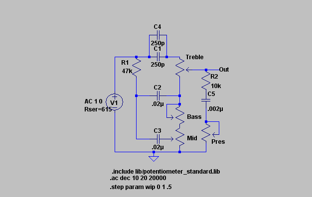
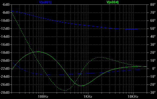
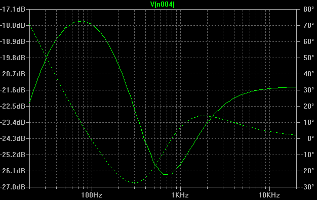
Why hello! It is our old friend, the Fender/Marshall tone stack, as it appears in a Marshall JCM800. If you look closely you'll see there isn't much difference between the Marshall circuit and the Nomad Ch3 circuit. 2 250pF caps in parallel effectively make a 500pF cap. The only other difference is the slope resistor on the input. The Nomad has 47k?, vs the Marshall's 33k?. That's it. The 30pF difference between treble caps isn't going to make anywhere near as much difference in the change in the slope resistor. I've never heard the Marhsall JCM800 described as muddy, in fact the common mods I see for the JCM are intended to fatten it up, implying it's thin, not muddy in the bass. Anyway, let's compare the freq response of these two circuits.

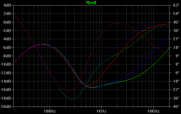
MarshallFreqResp.png
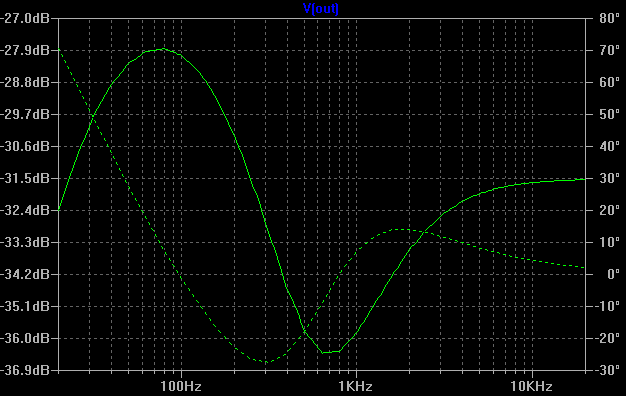
NomadFreqResp1.png

That's the JCM800 on the top, the Nomad on the bottom. And what the--. The higher value slope resistor decreased the Channel 3 bass relative to the tight&bright JCM. And it's not like the Marhsall tonestack has an emphasis of the bass over the treble anyway. The bass peak is maybe 1dB higher. Okay, so the Treble Mids Bass circuit itself isn't the source of our mud. What about the presence control? The Marshall presence control is a high freq boost in the negative feedback loop, ours is a high freq cut that sits right off the tonestack 's output and could indeed be considered part of it.

NomadToneStack2.png

Here's the presence control as it appears in the schematic added to the simulation

NomadFreqResp2.png

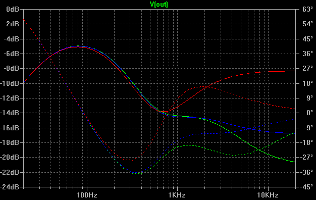
And here's the change in frequency response with the presence control, set on full, half or off. As we can see, it can potentially suck out all the highs, and some of the upper mids, depending on where the treble control is set. Pay close attention to the red line. There, the presence control is having it's minimum effect on the tonestack. Yes, the treble is down from the bass, but it is only down -3dB down from the almost perfect balance we had before. So while the presence does have an effect on the circuit, it isn't sucking away enough highs to make mud unless you've turned it too far down.

NomadFreqResp2a.png

The higher the treble is dialed, the less highs the presence control will take out and the more it's effect will be limited to the upper mids and lower portion of the highs as seen in this graph. The presence control can't take out the very top of the high-end, even when it's turned all the way down.

There's another difference between the Nomad and the JCM when it comes to the tonestack. In the JCM, the tonestack is driven directly by the cathode follower. There isn't even a coupling cap between it and the tone stack. However in the Nomad, we have a small network of caps and resistors between the the cathode follower and the tone stack. So lets ad those to the simulation and see what effects, if any, they have.

NomadToneStack3.png

Here's the simulation with the cap/resistor network between the cathode follower and the tone stack as it appears in the schematic.

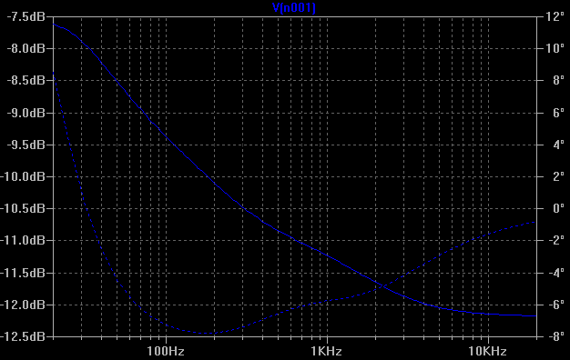
NomadFreqResp3a.png

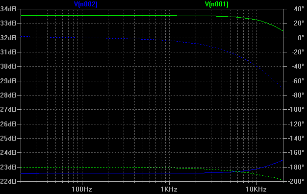
Here is the frequency response of that network alone. Uh oh! More high frequency attenuation! By 10kHz, we're down about -4.5dB. However, this is different from the treble bleed in the FX loop. This is a gradual attenuation, all the way from the bottom of the bass to the top of the treble, with an ever so slight bump in the upper mids (said bump is probably negligible, tonally). The FX loop keeps all the bass and low mids and rolls off everything else. It is worth noting that shrinking the size of the treble bleed capacitor has no effect on the shape of the slope and a negligible effect it's magnitude. Tweaking the network doesn't net any real changes until the resistor sizes have changed drastically, and then it doesn't cease to roll off high frequencies. Instead, it turns into a boost in the low mids. If we're trying to reduce mud, boosting low mids is counter productive. If we don't like the effect this network has, the easiest thing would be to just cut it out of the circuit and bypass it. Another thing to keep in mind is that this cap/resistor network sits between the cathode follower and the relay that selects the channel 2 or channel 3 tone stack, so it equally effects both channels. If you find channel 2 muddy but not channel 3, or vice versa, this network isn't the source of your mud.

NomadFreqResp3b.png

Here is a comparison of the network's attenuation and the tone stacks' response. The highs and the lows in the tonestack itself remain are still as they were with the presence. The only real change is now the overall response of the tonestack is now attenuating the signal more than it did without the network.

NomadFreqResp3c.png

Here is now the whole tonestack's response, from input to output. Don't let it fool you. Treble is still only down about -3dB as it was before with just the presence control added to the circuit.


There's one last bit I want to cover that affects the tone stack's response. The vintage/modern switch and the master volume.

NomadToneStack4.png

Here is the final bit of the tonestack, the volume control and the modern/vintage switch (it controls a bypass around the 220k? resistor and how the reverb is blended back in. That's it.). The only thing missing from this simulation now is the reverb, which is beyond the scope of what we're trying to find: does the tonestack cause the mud? Here's the EQ response of both modes.

NomadFreqResp4b.png

Vintage

NomadFreqResp4a.png

Modern

And it appears that the 220k modern/vintage resistor has no effect other than further attenuating the signal. The frequency response doesn't change. But in Modern mode with the resistor bypassed, the tonestack reacts to the master volume, bringing the treble back up. Whether the master volume is attenuating bass, or the 220k resistor is attenuating treble (probably both), the effect is that in Modern mode, balance between treble and bass is is pretty much restored to what it was before we added the presence control. And it's louder too.

At this point, I don't know that drastic changes to the tonestack beyond moving the presence control from the tonestack to the feedback loop will be effective. Furthermore, the tonestack for channel 2 overall has even less bass response because of a larger slope resistor, and yet it is by far fatter sounding than channel 3 because of how the preamp is configured. Also, nomad100hd said how the Nomad preamp was lively and without mud when run into another power amp, so it is entirely possible that the preamp, tonestack included, is fine as is. If we want less mud from the Nomad, moving the presence controls to the negative feedback loop where they belong should be the first step, and if that isn't enough, tweaking the FX recovery stage for a more even treble response should come next.
 
there is no grid stopper on the input triode of the mesa nomad. If the layout of the board is prone to occilation that cap maybe needed. Compare the schematics of the a lot of none mesa amps and u wont see so many caps dumping highs to ground. Those are at least my thoughts on it. would just be easier to strap a cap over the load of each tube stage if u were worried bout occilation :D Nice work with the tone stack, i'll look it over more when it's not so late
 
Well, the input stage does even better, there's a ferrite bead on the bead on the input. It adds inductance, which when it comes to frequency response, acts opposite to a capacitor. If a cap permits treble and blocks bass, an inductor blocks treble and permits bass. Put it in series with the input and high frequency noise gets blocked, dissipated in the ferrite bead. The rest of the stages do have grid stoppers, but that's probably more for tone shaping reasons. I'd still prefer to err on the side of caution when it comes to removing treble bleed caps from the circuit. They're there for a reason.
 
The Nomad mod thread lives again. Thankyou Koreth! Outside the usual disparaging remarks it's been pretty boring here lately for us Nomad users. Very cool info! Unfortunately, I also rely on mine too much to disect it right now. It would be great to hear the results if someone does try the things you've mentioned. Keep us posted!

Joe
 
Back
Top