Help identifying Mark Series [CUSTOM RESTORATION]

The Boogie Board

Help Support The Boogie Board:

This site may earn a commission from merchant affiliate links, including eBay, Amazon, and others.
Next is the power amp PCB. Since I had the original PWR-7C board de-populated I could follow close(r) the stock component positions, except with (of course!) my own improvements:

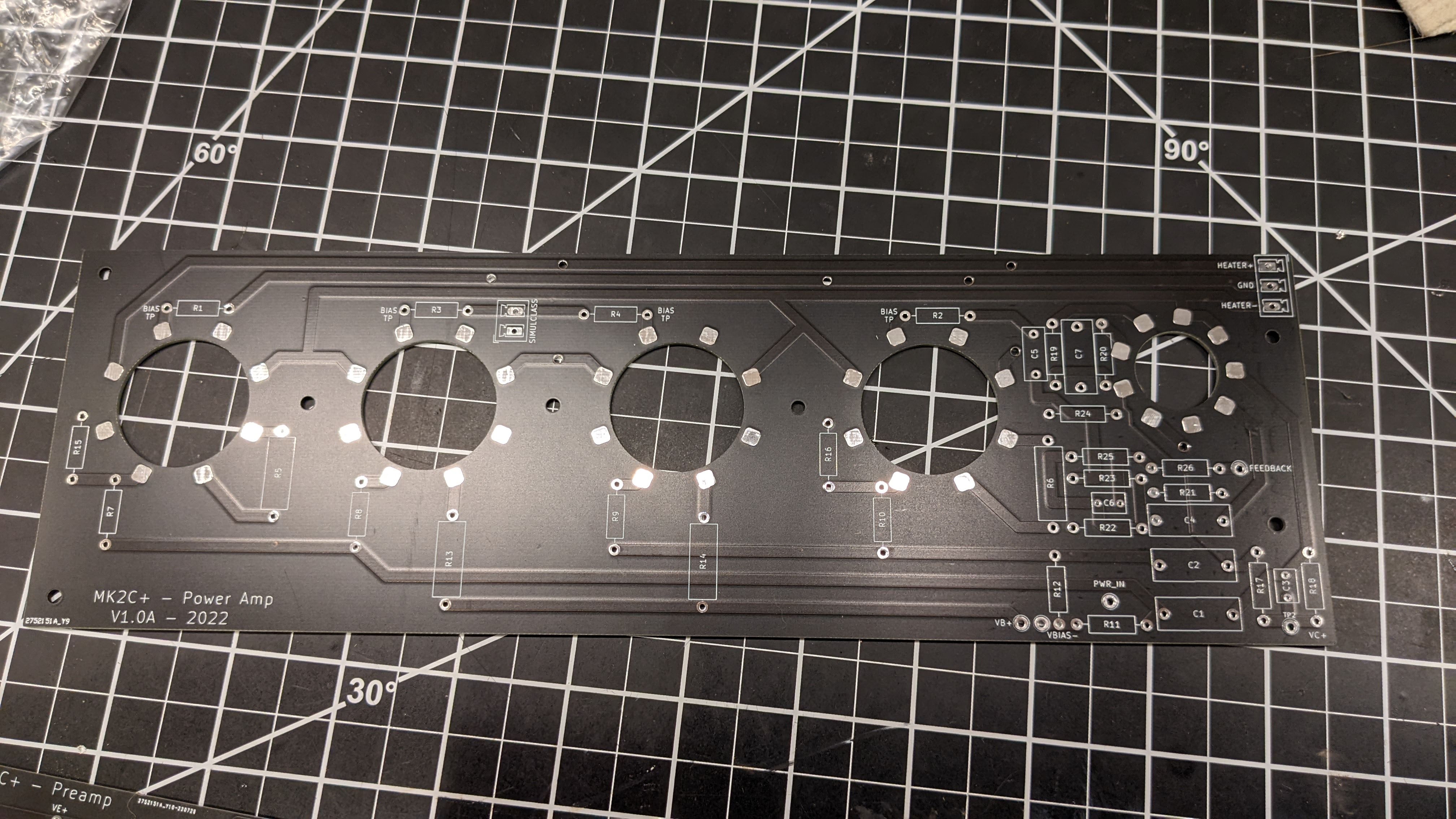
  1. NO DIRECT SOCKET SOLDERING TO THE BOARD. This is the most common failure mode on these amps, which is either a) a cracked socket, b) a broken socket pin, c) a lifted trace, or d) heat damage from the output tube to the PCB. Sockets will join to the board through short wire jumpers to mechanically decouple the sockets from the PCB. PCB is spaced 0.5" away from the chassis.
  2. 1 ohm cathode resistors are added to all 4 output tubes to facilitate biasing/balancing.
  3. Added more horizontal space so components don't need to be under other components.
  4. Screen resistor layouts are increased to accommodate 3W resistors.
  5. These are two layer boards, so no wire jumpers needed (jumpers are on the bottom layer now).
If the board needs to be replaced, the "pigtails" can be removed from the board easily, and the entire PCB can be removed without too much fuss without disturbing the sockets at all. These boards are 2mm thick (80 mils) with 2oz copper, so are much more rigid than the originals.

power_amp_pcb.jpg
 
Next is EQ PCB.

Not so many changes here.

  1. Switched transistors to TO-92 ECB layouts, using MPSA06 and MPSA56 NPN and PNP transistors, rated at 80V. Beta is similar to original MPSA70 / MPSA20 transistors.
  2. Axial caps were switched to radials.
  3. The dominant-pole compensation capacitors were moved to be more clear of other components, as these are usually what need to be tweaked to cure oscillation problems.
  4. The LDR that turns on and off the EQ (LDR5) is moved to this board, and off of the preamp board.
I'll note there that I wanted to change this whole mess to a simple op-amp but the customer was dead-set against it. :D
eq_pcb.jpg
 
Finally the preamp board.

This has a bit different layout, however those familiar with the original RP11A will feel at home where things are placed.

  1. Obviously all of the channel switching stuff is missing.
  2. No direct socket soldering just like the power amp board.
  3. I had to take some poetic license with the routing, as I didn't have a de-populated RP11A board to trace.
  4. Reverb circuitry added in.
  5. The '++' modes are added in, and placed on 0.1" jumpers. Thus you can add and subtract the mods by placing or pulling the jumpers. Not as good as having them on a front panel, however I haven't found many (e.g. any) players that needed to swap back and forth while playing.
  6. Any components that would normally be soldered directly on the pots are moved to the board. I HATE removing and redpoing this stuff in order to replace a pot.

preamp_pcb.jpg
 
More progress! Got the boards stuffed (minus a handful of components I'm waiting to arrive from being backordered). Now that I can mount all of the PCB's in place I can get an idea of how to route the wiring.

PXL_20220914_215716219.MP.jpg


But everything is in place, and everything fits properly. I substituted LED's in for the various LDR connections, and confirmed:

  1. The lead channel switch properly switches on LDR1,2,3, and 4
  2. The green LED is lit when using the normal channel (my own addition)
  3. The red LED is lit when on the lead channel (my own addition)
  4. The EQ LDR5 is active when a) EQ switch is up, b) the EQ footswitch is enabled, and c) when in 'Auto" mode and the lead channel is enabled
  5. I get ~450V on VA+, VB+, VC+, VD+, and VE+ when there is no load
  6. Virtual center tap for the floating heater bias is 45V (my own addition)
  7. The VEQ is at -80V with no load
  8. The negative bias is adjustable between -25V and -65V (my own addition)
I need to wire up the power, standby, and fuse, and then when my octal sockets come in, I can wire up the power amp board and output tube sockets and test that next.
 
Back
Top