395 bias mod?

The Boogie Board

Help Support The Boogie Board:

This site may earn a commission from merchant affiliate links, including eBay, Amazon, and others.

UglyNoize

Member
Joined
Aug 9, 2016
Messages
8
Reaction score
0
Has anybody added an adjustable bias to these amps? Google is no help in this case...

I just got a 395 with nearly brand new JJ tubes all around pulling... Wait for it... 3mA of current... So needless to say, that's gotta change. I'd like to install just a single bias pot to bring everything up to an acceptable bias range if possible. Is this possible, and if so, what resistor would have to be changed to a pot?

Thanks!
 
Can anybody at least point me to a schematic of this amp? I can't seem to find one online.

Thanks!
 
If that's the reading you are getting, something is not right, and a bias mod should be the leasy of your worries. What voltage are you getting on the plates?

Either the meter is wrong, or the way you are checking is wrong. Or the power tubes are defective or worn out completely. Or the amp is damaged or defective.

Take it to a Mesa service tech, or one you trust. Something is WAY off, I suspect a ground wire is loose, or something in the power circuit is messed up.
 
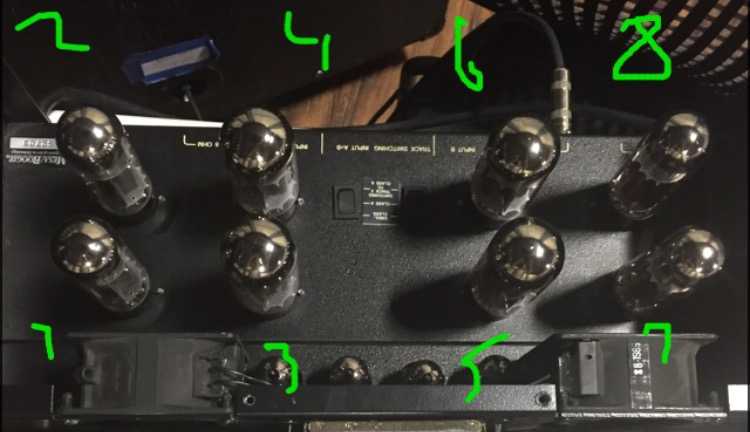
Since I was unable to find a schematic online, here's how I've labeled the tubes

0vPGLb.jpg


V1, V2, V7, and V8 are all JJ EL34L, all others are JJ 6L6GC. All were very recently installed, and was only lightly used in with a TriAxis rig that was a backup/studio rig for a local musician. The issue is that these tubes were not spec'd for a Mesa like they should've been. This isn't the first time I've seen readings like this from a Mesa under similar circumstances, but was always able to fix them with either a bias mod or a hotter set of tubes. However, I haven't got two hot quads to boot, and don't have the funds for a retube at the moment.

With all of that out of the way, here's the complete rundown. All plate voltages were taken from pin 3 of each socket, and all currents measured with a bias probe.

V1: 499V @ 4.7mA
V2: 500V @ 5.2mA
V3: 501V @ 6.6mA
V4: 501V @ 6.2mA
V5: 502V @ 6.2mA
V6: 502V @ 5.8mA
V7: 502V @ 2.9mA
V8: 500V @3.9mA

EDIT: I'd also like to add that the amp does appear to be bone stock on the inside, and is in very good shape internally. I couldn't find any loose connections, blown resistors/caps, or any physical damage to the PCB. Will post pics on request.
 
I'm not sure which method Mesa uses to set bias, but there are differing ways to measure based on circuit design...

https://robrobinette.com/Tube_Bias_Calculator.htm
 
Most every Boogie I've owned or done work on has had a bias that is set with a resistor, or have been cathode biased. However, with it being two amps and not having a schematic, I don't know if it's a single bias circuit, or two, or even four since it's a simulclass amp. That's really what I'm needing to know: Which resistor(s) set the bias?
 
If you've worked on Mesa amps before it is very easy to follow the layout and figure out which resistors need to be replaced.

It will be two of them. The power transformer is shared but each side has its own complete circuit after the main voltage.

Look for the pairs of 47uF 100 volt electrolytics like they use in all of there amps and the resistors are right in that area on each side of the board.

I've done it to my strategy 500 in the past and have a 395 on the way so could give better descriptions once the amp is in front of me.
 
Thanks timv, exactly what I was needing to know.

Are the bias resistors 56k like the Mk III?
 
Alright y'all... The deed is done. Biased these puppies up to 35ma and they're SCREAMIN' now :twisted:
Here's a mini tutorial for the next guy who lucks on a 395 with cold tubes and turns to the Internet for answers...

Here's what I did, completely non-intrusive, and only requires some wire, a couple of pots, and a good iron. Some patience certainly helps too :mrgreen:

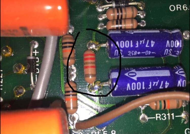
First I removed the 22k resistors tied to the two 47uf caps on both sides of the amp. They're mirrored on both sides, so finding the second shouldn't be a trick if you could find the first. Should look something like this:

AXYyM0.jpg


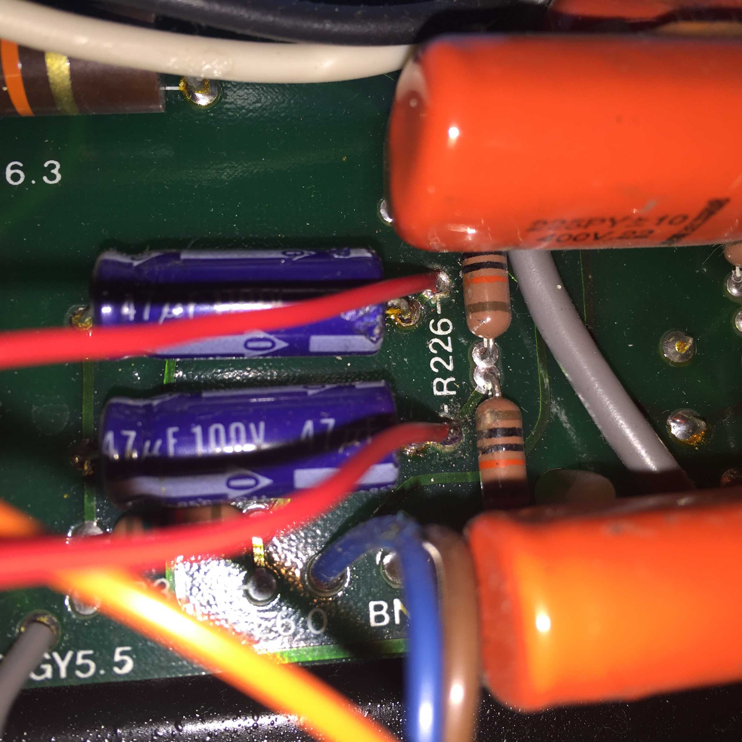
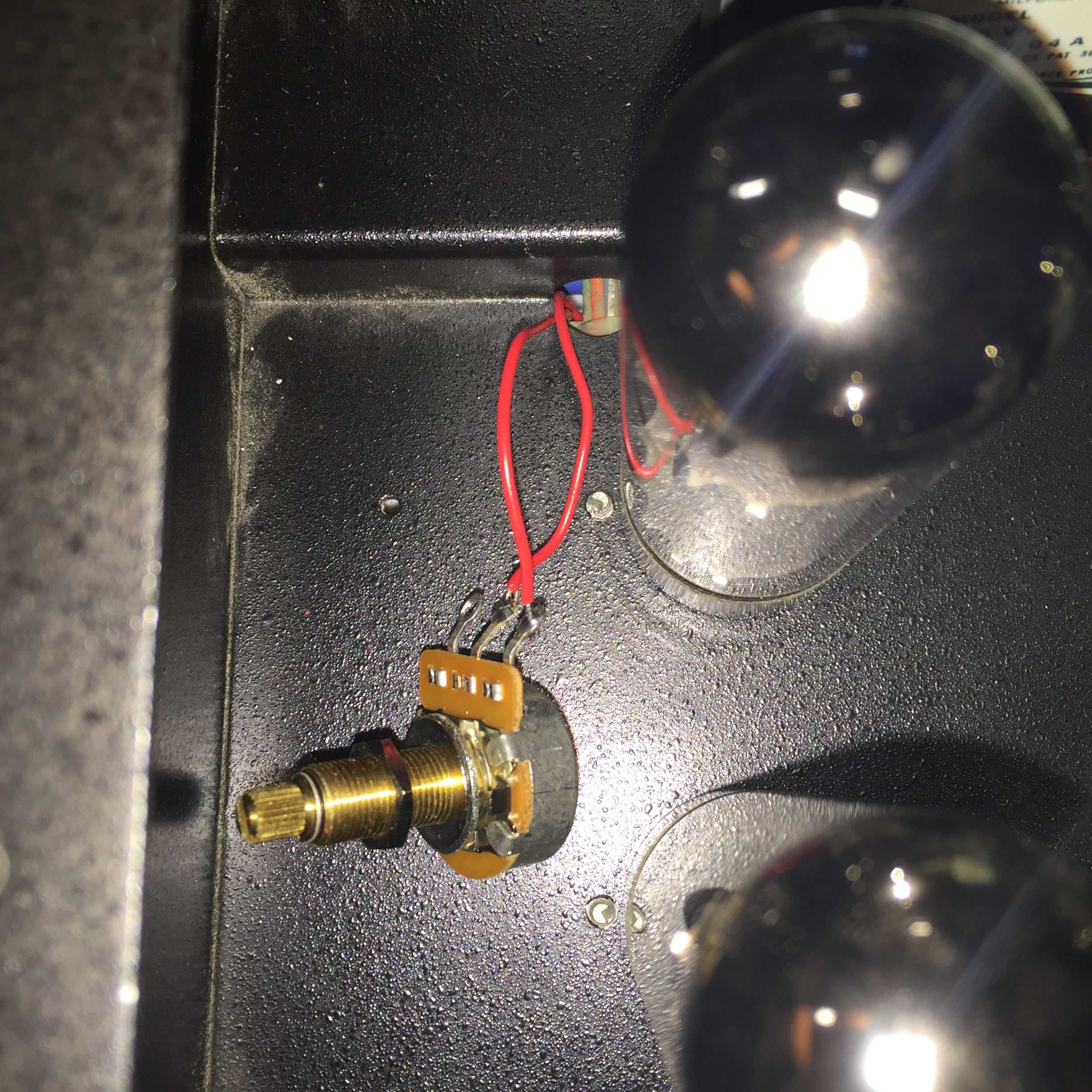
Then, I ran some wire to the empty resistor holes left by the 22k resistors, and flew those leads to two 250k pots (just what I had around, 100k would've worked better, I ended up at 65k of resistance) on the outside of the amp. The bottom wires of each socket were ran to the inner lugs of the pots, and the top wires ran to the left lug if looking at the pot from the front. The pots should be set to 22k between the left lug and center lug to avoid cooking your tubes crispy.

A pic of the flown leads:

zW9n41.jpg


... And the pot:

SDE6vC.jpg


Secure the pots as you see fit, I didn't have anything on hand at the immediate moment, so they're just hanging for now...

Then just grab the meter and bias. Nice and easy!

Hopefully someone can find some use from this thread and this halfa$sed tutorial.

Thanks for the help everyone!
 
The way I've always seen bias adjustments setup would have been adding a pot to that empty resistor spot labeled R311.

The resistor you replaced is the front end of the voltage divider and usually the adjusted value is the one that goes to ground.

I suppose how you did it does work but if the pot opens up, the bias voltage will go to zero and you're tubes will runaway.

If you put it across that R311 spot in parallel with the other resistor that is there, if the pot were to open you would be left with the other resistor and your bias voltage would go more negative and the tubes would run cooler.
 
I would use a lower value pot with a resistor in series, at least. You wouldn't want all those tubes to run away and possibley take some iron with them.
 

Latest posts

Back
Top