Mark V:90W FX send levels measured + others

The Boogie Board

Help Support The Boogie Board:

This site may earn a commission from merchant affiliate links, including eBay, Amazon, and others.

bandit2013

Well-known member
Boogie Supporter
Joined
Feb 22, 2013
Messages
4,113
Reaction score
526
Location
North Carolina
This is interesting but the test was actually annoying but I was able to set the global master to null to keep the single frequency from drilling into my head.
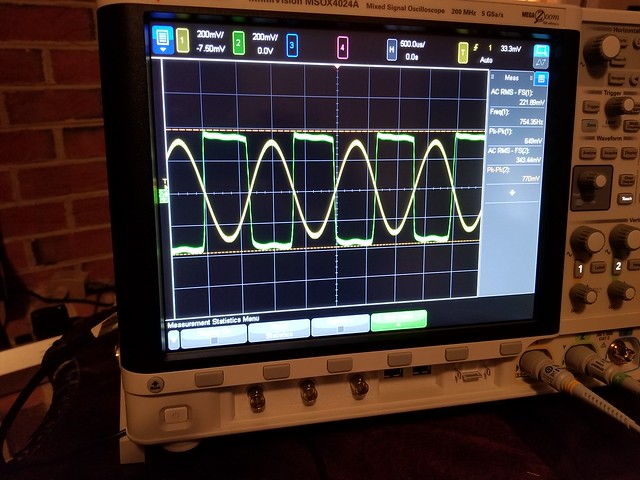
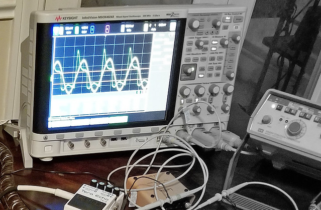
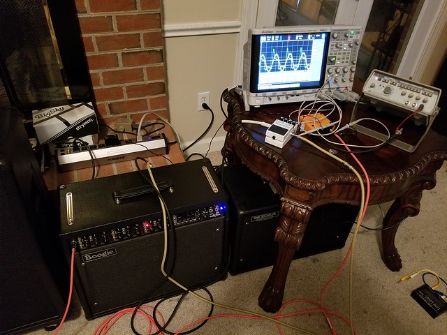
I had borrowed the better oscilloscope from work, a function generator and a few of the probes but did not need to use them. However the setup was quite easy, find two cables that did not have heat shrink on the soldered coax cable joints. For this test, I did use the Lehle P-Split 2 to provide isolation from the function generator and the Mark V amp. I dialed in a 640mV p-p signal fixed at 750Hz. The voltage was set to the average voltage measured with the guitar as the signal source (excluding the initial attack impulse). Since it is easier to convert from RMS to dbu and dbv units I set the scope up to display the rms voltage of the signal, the same was used at the FX Send. I also used a Boss Terra Echo in hard bypass mode in the FX loop and measured the send level at the input of the pedal. For each channel, I disabled the EQ function for the initial pass as that greatly influenced the signal level on the FX loop as well as added some distortion so I figured it best to leave it off and then followed through with the 5BEQ turned on in a V shape pattern, 750Hz slider was at center as this was the test frequency. The preset basically reduced the test frequency dramatically so it was not included. All three channels had the control settings set to noon. as for the mini toggle for each channel, Bold, Mark I thick (only effects mark I voice) and bright were set. Also the FX send level was at noon. Keep in mind that the measurements were done with a single frequency and will be much different with the guitar driving the amp. So use the measurements as a reference. Also note that the Master volume had no influence on the FX send level.

The empirical data is as follows:
Input voltage: 217.17mV rms fixed at 750Hz: 217mVrms = -11dBu

CHANNEL 1 influence on the FX loop
(5BEQ turned off)
Channel 1 - Clean: 2.70 dBu
Channel 1 - Fat: 1.36 dBu
Channel 1 - tweed: 5.82 dBu
(5BEQ turned on, V shape but with 750 at center)
Channel 1 - Clean: 4.50 dBu
Channel 1 - Fat: 4.11 dBu
Channel 1 - tweed: 4.27 dBu

CHANNEL 2 influence on the FX loop
(5BEQ turned off)
Channel 2 - Edge: -1.96 dBu
Channel 2 - Crunch: 1.88 dBu
Channel 2 - Mark I: -2.95 dBu
(5BEQ turned on, V shape but with 750 at center)
Channel 2 - Edge: 1.99 dBu
Channel 2 - Crunch: 4.10 dBu
Channel 2 - Mark I: 2.06 dBu

CHANNEL 3 influence on the FX loop
(5BEQ turned off)
Channel 3 - IC+: 3.722 dBu
Channel 3 - MKV: 3.50 dBu
Channel 3 - Extreme: 3.80 dBu
(5BEQ turned on, V shape but with 750 at center)
Channel 3 - IC+: 5.79 dBu
Channel 3 - MKV: 5.80 dBu
Channel 3 - Extreme: 5.81 dBu


37753549385_77e5db787f_z.jpg
[/url]
 
I also tried this with the Ebtech LLS-2 in the loop. Send to +4, Return to +4 and the two -10dB were coupled together with a jumper cable. Input and outputs of the Ebtech LLS-2 were matched. I also compared the signal attenuation on the -10dB circuit. It is 25.5% of the Send level.

Interesting. With the Mark V FX loop compared to a hard bypass vs the Ebtech LLS-2 there seems to be some loading on the signal. The Ebtech does reduce the signal strength by 23% compared to the pedal Boss pedal in the loop. A boost can be added after the Ebtech if possible (do not use it in the -10dB section as that will add noise.)

When I tried the Ebtech LLS-2 in the TC-50 loop, I did not experience any signal loss at all and did not seem to be any difference running direct or with the Ebtech device in the loop. This would be an impedance issue with the Mark V as indicated in the written report on the G-System boards and how to overcome the signal issues with the Mark V and G-System.
 
The question is now this, How do the other amps compare? I will get to that tomorrow if there is enough time to do it. My guess is that the FX loop levels would be much lower than that of the Mark V and compatible with instrument level devices. I will find out soon enough.
 
The Effects that I have used with out issue in the Mark V that I currently own.

Strymon DIG, Brigadier, Big Sky, Ola. All of these and most Strymon effects have a maximum input of +8dBu. Just look for the audio spec on their website. I also looked at the Boss pedals including the New DD-500. +8dBu mximum input, Terra Echo can support far more at 20dBu. All of these will work just fine with instrument level fx loops and instruments too if you like it on the front end, but why not use it in the loop.

When Selecting a delay or other effect to be used in the Mark V FX loop, look for the specs for the input levels. If it is not stated in dBu anywhere, it is not compatible with line level signals and will most likely be instrument level only for -10dBu or lower. However some guitars with active electronics may push 1.47V peak to peak, this would be equivalent to 520mV rms or -3.4dBu. My Carvin DC400 with active tone controls wen used is about that in voltage, switched off it is more like the signal used in the test 750mVp-p or 265mVrms.

In case the device you are interested in is stated in (x)dBv the calculator will convert that for you in terms of dBu, Vrms, or Vp-p

link for the calculator if you want it.
http://www.sengpielaudio.com/calculator-db-volt.htm
 
I checked the JP-2C send levels and the TC-50 send levels. The JP-2C seemed to have limits on how high the send level would get. I started with all controls at noon with the exception of the channel master volume as that had no impact on send level on the FX loop. Also it saved my ears from the single tone at 750Hz that would have been worse than a visit to the Dentist. I did sweep the gain and other controls, turned on and off the EQ and did not see any abrupt changes in send level. Not sure what the limits on an instrument level pedal would be, typical is -10dBu unless that is specified in dBv.

Here are the measured signal levels on the JP-2C (all controls at noon)

CH1 - clean: -5.09 dBu (-7.31dBv), actual measured ac voltage: 431mVrms (sinusoidal with slight distortion)
CH2 - lead: -7.17 dBu (-9.39 dBv). actual measured ac voltage: 221mVrms (not sinusoidal, soft square wave)
CH3 - lead: -6.97 dBu (-9.13 dBv), actual measured ac voltage: 339mVrms (not sinusoidal, soft square wave)

26883797409_3caeebdfdf_z.jpg


The TC-50 was a completely different animal in respects to signal levels. For this I was able to null the global output to save my ears and prevent unwanted howling from the dog. The clean channel posed more of a challenge as it was found that both the channel volume and gain influence the signal level on the send jack. (this is also the case with the other two channels but due to compression of the signal caused by clipping the output levels remained much lower than 0dBu.

Clean channel: Gain and Volume maxed: 8.17 dBu. Yeah, that may clip a Strymon pedal. actual measured ac voltage: 1.966Vrms (sinusoid with some distortion evident) I did not try the drive switch, left it at normal. 8.17 dBu = 5.87 dBv.
For typical settings: Gain and Volume set to 2pm: -1.75 dBu [-3.97 dBv], actual measured ac voltage: 633mVrms

Both the lo and high gain channels remained consistent, almost comparable to the JP but a bit higher in signal levels. I had set both channel volume settings to 2 pm and both gain settings to 3 pm.
CH2 - lo gain : -4.77 dBu [-6.99 dBv], actual ac voltage: 447mVrms (not sinusoidal, soft square wave with some peaks on the leading edge)
CH3 - hi gain : -5.15 dBu [-7.37 dBv], actual ac voltage: 428mVrms (not sinusoidal, soft square wave with some peaks on the leading edge).
 
Interesting results. It will take a while to digest them.

It seems the different channels on the amps all do different things to that 750 Hz sin wave. Would it be possible to generate a “guitar white noise” (even level white noise in the freq. range of the guitar, say from low E up to high string 19th fret B? Then, pump that white noise through the amp and measure the voltages? This way, the voltage reading would be less sentive to what the channel settings or EQ settings are. Of course, I could be wrong about that (I’m no EE). And, your time is probably limited as the weekend is up!

Thanks for doing these experiments and sharing the results.
 
The thing about distortion and non-linear triodes, when you have more than one frequency in the mix, it becomes difficult to narrow down the effect. Non-liner gain will become additive and subtractive in the range of frequencies. I was trying to focus on one frequency to determine the actual amplitude of the send level. I could have used 1kHz, or any other frequency but felt that the most influential frequency would be around the center of the 5BEQ as the deal was to remove it post gain. "V" pattern. Besides, the 1KHz frequency was more annoying than the 750Hz, even that was getting on my nerves as it was audible though the speaker even though the Global volume was all the way off. Interesting to note that the single frequency was more of a square wave on the JP-2C (quite similar to when I had done the same thing with the Mark III some 20 years ago). Typical shape looks like a square wave but with a "w" shape on the bottom and a sloped line on top with smooth rounded edges. The TC-50 had a similar shape but with some hooks on the leading edge and more of a slope on the flat areas of the square wave. The distorted waveform from the Mark V was not even square, it was more of a cluster ***k. Next time I will capture the waveforms from the power amp instead (but that will not help understand the send level of the FX loop).
 
The comments about the Mark V and JP-2C wave form differences are interesting, that one was defined and the other was a cluster of sorts. Was this when the Mark V was in IIc+ mode? Did pentode or triode make a difference? It would seem one would expect the distorted wave forms of an actual IIC+ (like the JP) to be close to the IIC+ mode on the Mark V. Or, at least, one could dial in the Mark V IIC+ mode to get a similar looking wave form.
 
I did not capture the power amp signal, only the send level signal. Pentode or triode would not influence the send level signal by any means. The same would be true for the presence control as the feedback circuit will never make it to the preamp since the feedback is inserted at the phase inverter.

Perhaps I will borrow the gear again this weekend for some other testing. However, the waveforms from the IIC+, Mark IV and Extreme were not that much different from each other. This next go around I will capture the waveforms of each voice on the Mark V, JP-2C and the TC-50. I was only interested in the signal level than the waveform shape.

I zoomed in on the one image of the Mark V focused on the scope. This was with the Extreme mode selected on CH3. The green waveform was the Send level signal. Note the sharp rise on the leading edge of the waveform (left part) I believe this to be a harmonic of the 750Hz signal that seems to be dominant. Hard to say what the distortion content is (harmonics wise) as I do not have a signal analyzer at my disposal as well as I did not take home the computer that has the licensed software for analysis and data logging with the oscilloscope. the yellow signal was the 750Hz sine wave (the one that is not distorted, the green and yellow waveforms may be hard to distinguish in the image due to brightness of the screen). The IIC+ and the Mark IV signals were similar in shape but at different signal levels and perhaps phase relationship may have shifted. So the side effect of the cascaded gain stages from V1 through V6 and after the EQ can be shown.

26922957889_b812f80e63_z.jpg


To capture the power output waveforms is quite a different task and very hard on the ears. That reminds me of something my father said. "what is the definition of perfect pitch?" "It is the sound a banjo makes when hitting an accordion at the bottom of a dumpster." Also I did not have proper PPE or Personal Protection Equipment to run the power section at a single frequency, aka "ear plugs" as that will be required if I want to get into the amp sweet spot.

If I do decide to run comparative tests on the distortion characteristics of different amps, that is out of the scope of this thread as the intended purpose was to reveal the signal levels of the FX loop and what would be needed to use it as far as specifications for an effect used in the loop. If your device is +8dBu or higher, you should not have any issues in terms of input buffer overloads or clipping.
 
Back
Top