Does anyone know the spec of the LSS footpedal internally? I'm having a smaller one built to free up some space on my board, but can't get to the innards of the pedal to take a picture for the builder. The side panels come off easily, but the black main panel doesn't seem to want to slide out.
You are using an out of date browser. It may not display this or other websites correctly.
You should upgrade or use an alternative browser.
You should upgrade or use an alternative browser.
LSS footpedal
- Thread starter timmerel
- Start date


Help Support The Boogie Board:
This site may earn a commission from merchant affiliate
links, including eBay, Amazon, and others.
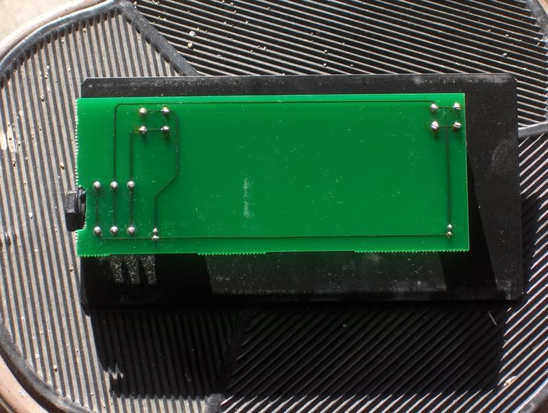
That odd. I unscrewed the side panel on my LS Classic footswitch and it slid out no problem. The whole black panel is a printed circuit board with the switches and jacks hard mounted on it. Maybe pull a bit harder?
I'm planning to shrink mine to fit my pedal board also!
I'm planning to shrink mine to fit my pedal board also!
plan-x
Well-known member
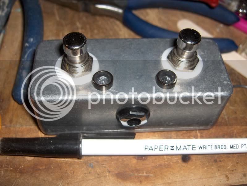
Maybe this will help. (LSC footswitch) I built one in a Hammond 1590A enclosure. Like half the size of a mxr enclosure. Those mesa FS's take up alot of real estate.
plan-x
Well-known member
Not really. My amp is down at the Church. Why do you need the voltage? For the LED's? I think on another amp I had to put a resistor in to reduce voltage, but I don't remember if I needed them for the LSC. I don't think there were any on the circuit board which I just copied the traces with wiring. These will work fine and shipping is dirt low. Grab a couple of bezels too. They've got the enclosures as well. http://www.pedalpartsplus.com/mm5/merchant.mvc?Screen=CTGY&Store_Code=PPP&Category_Code=LO5Mork said:John- can you tell me the voltage to the footswitch? Thanks.
I used these switches.
http://www.pedalpartsplus.com/mm5/merchant.mvc?Screen=PROD&Store_Code=PPP&Product_Code=9001&Category_Code=SWI
I can shoot a gut shot pic of mine later tonite after practice so it will be easy to replicate.
Updated with complete list of parts 11-13-09
Jack
http://www.pedalpartsplus.com/mm5/merchant.mvc?Screen=PROD&Store_Code=PPP&Product_Code=6007&Category_Code=JAC
Enclosure, Their are several choices for enclosures, pick one that suits your size needs
http://www.pedalpartsplus.com/mm5/merchant.mvc?Screen=PROD&Store_Code=PPP&Product_Code=1113&Category_Code=ENC15
plan-x
Well-known member
I'll see what I can do. I usually blow a few LED's while guessimating between to bright and not bright enough. Btw, nice stuff on your myspace. I requested you.
Btw, nice stuff on your myspace. I requested you.plan-x
Well-known member
Here's the scoop. As I remembered, the original LS FS had no resistors. The voltage must be stepped down from inside the amp. I did another amp's FS that had some resistors in their FS. That's the one I had to play with (frying a couple LED's) and ended up with about a 4.5K as I recall. Anyways, I just copied the LSC original with no resistors and it works like a charm.
This is the smallest I could make it.
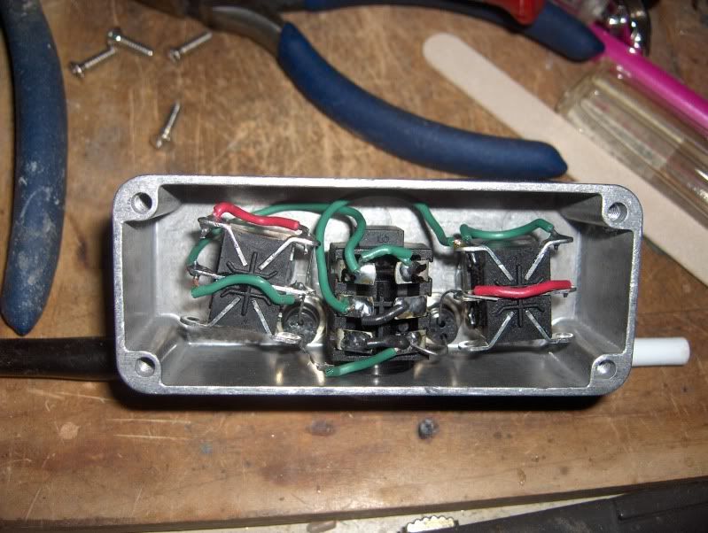
And the gut shot
This is the smallest I could make it.
And the gut shot
Wow! that's tiny! I might have to rethink the size of the enclosure I bought (about the same size as the Barber boxes) I like the idea of stomping on both switches at the same time, could be useful to cut down the tap dancing.
Anyway, thanks for doing that, very useful. Nice tidy soldering as well Hopefully the parts will arrive in a few days as I'm itching to tidy up my board.
I might have to rethink the size of the enclosure I bought (about the same size as the Barber boxes) I like the idea of stomping on both switches at the same time, could be useful to cut down the tap dancing.Anyway, thanks for doing that, very useful. Nice tidy soldering as well
Hopefully the parts will arrive in a few days as I'm itching to tidy up my board.fyi: the mark series (1-3) use a 3.3k, so maybe they're the same thing...plan-x said:That's the one I had to play with (frying a couple LED's) and ended up with about a 4.5K as I recall.
I don't think my sasquatch feet could hit just one of thoseThis is the smallest I could make it.
Very strange but the new footswitch won't work! My tecchie guy has wired it up, the channel change works fine (you can hear the relay trip) but the solo doesn't work. Seems like it's resistance that makes it work. Have tried different resistor values on the LED but not there yet.
Apparently all LED's need a resistor, some have them built in, that's why it looks like they don't have one...
Apparently all LED's need a resistor, some have them built in, that's why it looks like they don't have one...
plan-x
Well-known member
No resistors needed. Copy the original exactly! The parts got to be correct like the ones I linked. Including the TRS jack housing and it's wiring. Got a pic?
plan-x said:No resistors needed. Copy the original exactly! The parts got to be correct like the ones I linked. Including the TRS jack
All working now thanks
djw
Well-known member
John, thanks for the specs & pics on this, I just ordered a bunch of parts from Pedal Parts Plus. It's a DIY kinda time. It'll be fun to put this all together. Woo hoo!
plan-x
Well-known member
Have fun with it but don't inhale the solder fumes to much. :lol:
- Joined
- Apr 13, 2007
- Messages
- 23
- Reaction score
- 0
This is an older thread, but wanted to chime in. I just did some experimentation and the circuit is very simple. The two switches connect to a common ground. I measured the voltage one each positive channel at 11.5 Volts, so the LEDs definitely need a resistor in line to keep from popping. I think... I know a straight 9volt will blow an LED, but maybe the amps are a lot lower? Need to measure that and find out. It appears there are no resistors in the MESA footswitch.
The way MESA utilizes the two way switches is pretty cool. You really only need to use one throw, but they use two throws in tandem on each DPDT switch. It adds redundancy so that if for some reason one side of the switch fails, the other one side will do the work and the overall footswitch won't fail completely. Good engineering!
I am simplifying things a bit I only have two single pole switches. I am using a standard open RCA stereo jack. I am going to house it in a small Hammond MXR sized enclosure. Just a bit bigger than what Plan-X did. I want a little more space between switches, but I'l still be able to stomp them at the same time if I need to.
- Joined
- Apr 13, 2007
- Messages
- 23
- Reaction score
- 0
Update: Plan-X is correct, no resistors needed.
Similar threads
- Replies
- 3
- Views
- 2K