New .22+ Studio owner with technical questions...

The Boogie Board

Help Support The Boogie Board:

This site may earn a commission from merchant affiliate links, including eBay, Amazon, and others.

Bugeyed Earl

Member
Joined
Oct 5, 2013
Messages
23
Reaction score
0
Location
South Florida, USA
Hello all,

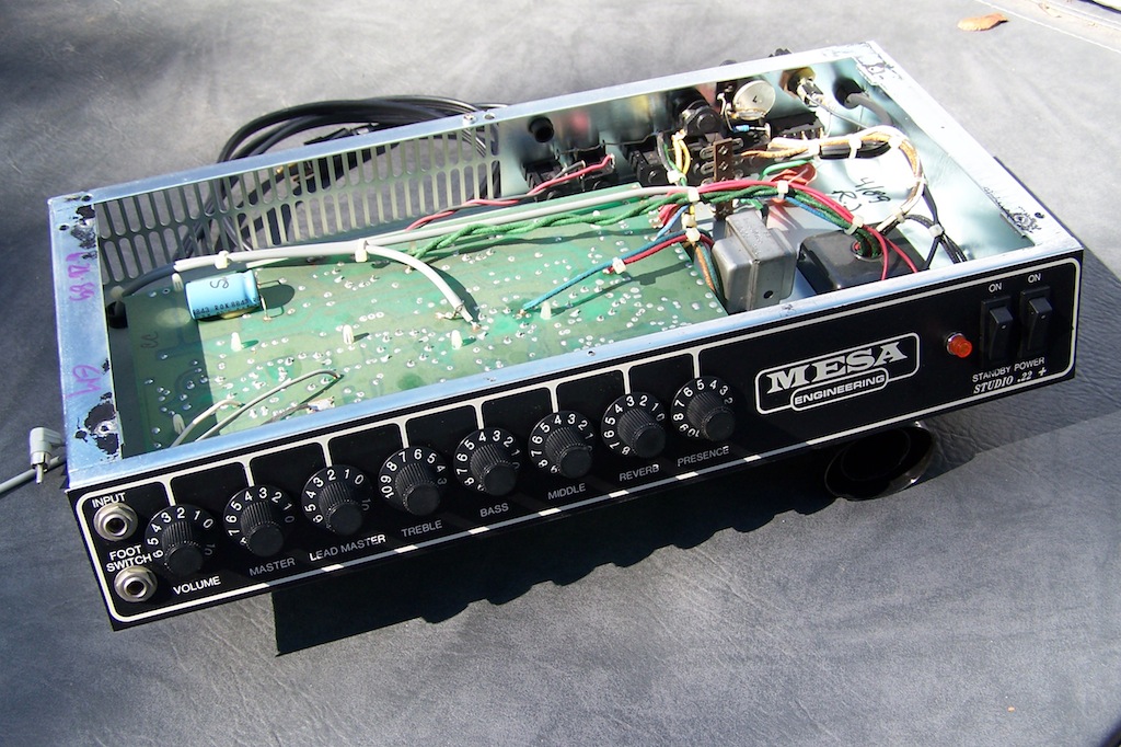
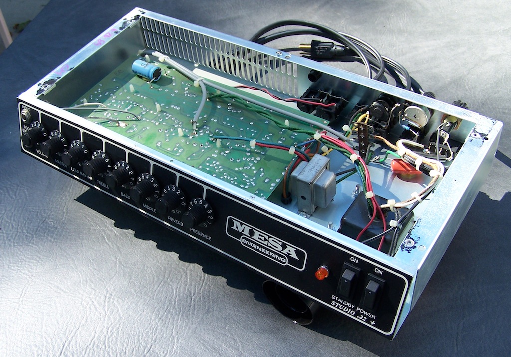
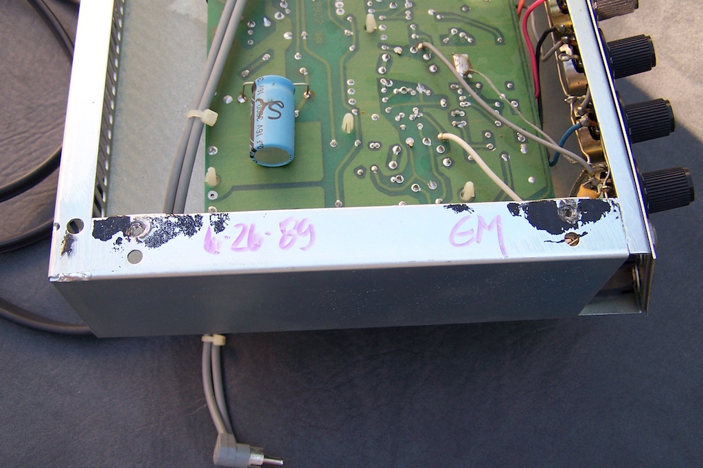
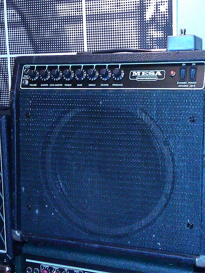
I recently horse traded my way into a .22+ Studio combo that I suspect will be a keeper, but it has a few minor issues I'd like to resolve. This unit has a build date of 1991 and no graphic EQ.

The original footswitch seems to engage the lead channel whether the switch (and LED) is on or off - I can only get to the clean channel when I unplug the switch. Touching the switch cable tip to ground engages the lead channel as it should. Oddly, I tried a Fender switch on the .22, and it worked fine, but the Mesa switch won't switch off the lead channel on the Fender. I opened the switch and didn't see anything unusual, it reads 0 ohms when it's switched off, but the amp still seems to find a path through the switch somehow.

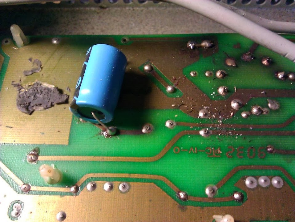
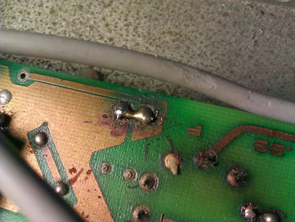
Digging deeper, I measured 41 volts at the footswitch jack on the Mesa. Is the 41v measurement on this circuit reasonable for this amp?

I found a few schematics on the internet, but I'm not convinced that I have a legit version. Does Mesa provide schematics on request?
 
That voltage seems very high. I just measured 8.25 volts on mine and it seems to function well.

There's a footswitch power supply diagram in the schematics. I'd make sure that all those capacitors and resistors look good.

The Studio .22 had a switching issue that was resolved by changing a resistor and cap but I thought it was resolved with the .22+.

There's a .22+ schematic on the web that shows this solution.

If you search here for Studio switching you might find more info.
 
Thanks a lot for the confirmation Don, I thought the voltage was a bit excessive. I pulled the chassis out this morning and found a few nasty looking solder joints and lots of debris on the main PCB that will need to be cleaned up. It looks like someone added solder to various points recently, I think I have a project on my hands :D
 
Yuck.

22combo_03.jpg


22combo_04.jpg


Whoever did the "touch-up" work in here had sloppy aim - practically everything above the PCB has scars from a hot soldering iron.
 
That needs some great love in there . Some shouldn t touch stuff when they don t know what to do .

Hope you can recover from the other guy s mistakes !
 
It's cleaning up pretty well, most of the debris was trapped in a layer of some kind of oily goo, I'm pretty sure it's fader lube that someone has been pumping into the pots. The oil was pooling pretty heavily on the tube sockets and the pins of the tubes. It turns out that the capacitor in the first photo is a 100uf/100v, when it should be a 3300uf/16v. :roll:

I also found this gem - check out the yellow wire on the right coming from the main speaker jack, and leading...

22combo_05.jpg


22combo_06.jpg


...nowhere!! It was floating between the chassis and the PCB, fortunately, not touching anything. I think that explains why the presence control has no effect.
 
I have some pics of the inside of my amp if you'd to see them. They're not as close up but might be helpful. Also, I'm opening up my amp soon to install a Lead Drive control and can take pics at that time if you'd like.

The 3300uF/16v cap in mine has radial leads and has been glued to the top of the PCB. It looks like yours has been replaced.

Good luck in your clean up.
 
That would be fantastic Don, I can't thank you enough!! I'm mainly focused on this loose yellow wire at the moment, I think it's indicated by the "FB" or "F8" callouts in the power section, but the print is a bit hard to read. The correct cap is on the way, hopefully that will resolve the footswitch issue. Thanks again!
 
It's probably "FB". That's the negative feedback wire. Unfortunately, I don't have a good picture of where it connects to the board.

I bought my amp a few weeks ago. When I pulled the chassis it looked like it had never even been out of the amp before!

These are the only pics that show the yellow wire at all and the last one shows the footswitch power supply cap.

100_9170.JPG

100_9174.JPG

100_9175.JPG

100_9177.JPG

100_9171.JPG
 
Don said:
It's probably "FB". That's the negative feedback wire. Unfortunately, I don't have a good picture of where it connects to the board.

I bought my amp a few weeks ago. When I pulled the chassis it looked like it had never even been out of the amp before!

These are the only pics that show the yellow wire at all and the last one shows the footswitch power supply cap.


Thanks anyhow, I think I see where it goes, but I'll trace out the circuit to be certain when I take the board out to replace the filter caps. Your amp is in amazing condition, it looks like new inside!
 
Bugeyed Earl said:
Don said:
It's probably "FB". That's the negative feedback wire. Unfortunately, I don't have a good picture of where it connects to the board.

I bought my amp a few weeks ago. When I pulled the chassis it looked like it had never even been out of the amp before!

These are the only pics that show the yellow wire at all and the last one shows the footswitch power supply cap.


Thanks anyhow, I think I see where it goes, but I'll trace out the circuit to be certain when I take the board out to replace the filter caps. Your amp is in amazing condition, it looks like new inside!

Will you do a full resto or just fix it .
 
Bugeyed Earl said:
Thanks anyhow, I think I see where it goes, but I'll trace out the circuit to be certain when I take the board out to replace the filter caps. Your amp is in amazing condition, it looks like new inside!

Thanks. It's a pretty clean amp. It even has made in USA Mesa power tubes in it.

As I said, I'll have it completely apart early to mid next week to install a lead drive pot and to move the reverb pot to the rear of the amp. I could take more pics at that time if you need them.
 
sprocket said:
Will you do a full resto or just fix it .

I'm planning to replace the caps and fix the
minor electrical problems, then enjoy it as-is for a while. It will probably evolve into a more extensive overhaul at some point (the ratty tolex will continue to gnaw at me...
 
Don said:
Bugeyed Earl said:
Thanks anyhow, I think I see where it goes, but I'll trace out the circuit to be certain when I take the board out to replace the filter caps. Your amp is in amazing condition, it looks like new inside!

Thanks. It's a pretty clean amp. It even has made in USA Mesa power tubes in it.

As I said, I'll have it completely apart early to mid next week to install a lead drive pot and to move the reverb pot to the rear of the amp. I could take more pics at that time if you need them.

That would be great, I haven't seen any photos of the other side of the board. I don't have enough playing time on mine to know if I want to do the lead gain mod, but it sounds like it's pretty popular, maybe that will go on the list...
 
Bugeyed Earl said:
sprocket said:
Will you do a full resto or just fix it .

I'm planning to replace the caps and fix the
minor electrical problems, then enjoy it as-is for a while. It will probably evolve into a more extensive overhaul at some point (the ratty tolex will continue to gnaw at me...

IMG_20131007_211458.jpg

Ok , it looks fairly good from poc , might not need much work to iy .
 
Thanks, and I agree, it's not really bad looking (and I didn't even see those nasty stains in the grill cloth until the flash lit them up.) The best part is that I got it essentially in trade for an old hybrid Peavey head that I bought a few months ago for $40. One of my best transactions this year :D
 
As a blues/rock guitarist, I need the ability to turn the gain down a bit on the lead mode while keeping it up on the clean mode. Currently, I'm turning down my guitar when I switch to the lead mode and turning it back up on the rhythm mode. I also might install a full size reverb tank on the floor of the amp but only if I hear a noticeable difference over the short tank that's in it.
 
sprocket said:
Bugeyed Earl said:
sprocket said:
Will you do a full resto or just fix it .

I'm planning to replace the caps and fix the
minor electrical problems, then enjoy it as-is for a while. It will probably evolve into a more extensive overhaul at some point (the ratty tolex will continue to gnaw at me...

IMG_20131007_211458.jpg

Ok , it looks fairly good from poc , might not need much work to iy .

Cool , you wont have much to do on it .
 
My curiosity got the best of me, and I tracked down the location of the loose wire on the board - it connects to the pad at L1 on the schematic (also marked with callout 4.) The guy who randomly touched up the solder joints apparently hit the pad above the wire, and didn't notice that it dropped off the other side. I replaced it and installed a new cap at C9, and it improved the footswitch problem, but not completely. There's still a noticeable bit of grit while in clean mode (but not as much as in lead,) and it only cleans up if I disconnect the pedal.

Now I read 21v at C9 in clean mode and 3v in lead, which is an improvement, but still higher than the footswitch update document indicates. I did verify that R131 & R115 measure to spec. I think I'll go through the rest of the footswitch supply circuit to see if I missed a bad component.
 
Back
Top